ENGLISH
30
30
OPTIONAL MODULES
The
City1
digital control unit, besides its excellent versatility,
provides for the final user with the possibility to add new
functions by means of optional modules. Its dedicated
connector has been placed over the word
OPTIONS
.
m
WARNING:
Please read the instructions of each single
module to install the optional modules.
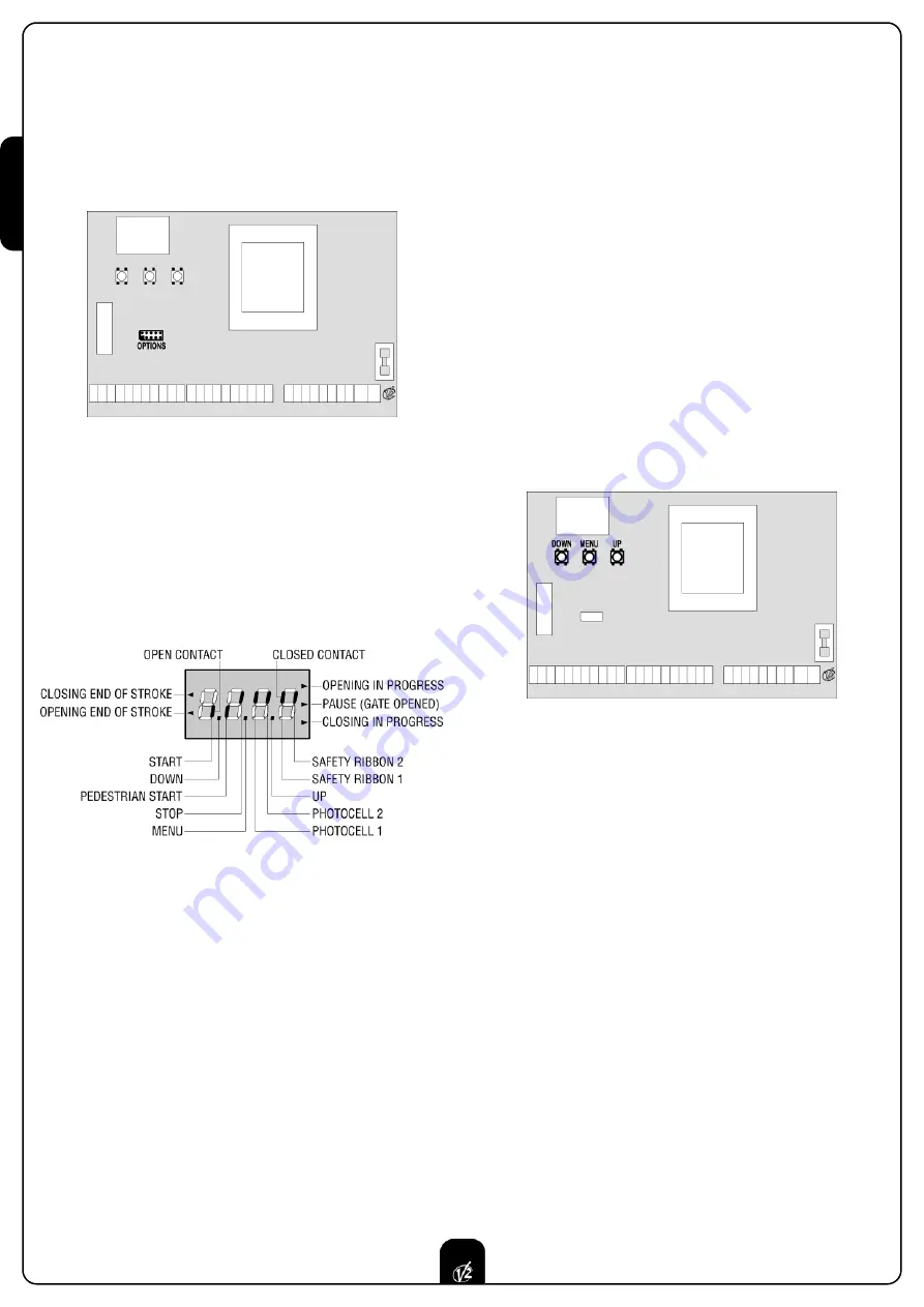
Connector for optional modules can also be used to plug in the
programming lock key (cod.
CL1
), which prevents from any
operation set-up change by non-authorized personnel.
CONTROL PANEL
When power is on, the control unit checks that display correctly
operates by switching on all segments for 1.5 sec.
8.8.8.8.
Firmware version, e.g.
Pr I.8
, will be viewed in the following 1.5
sec. Panel will be viewed upon completion of this test.
The control panel represents the physical status of the
terminal board contacts and of the program mode keys: if the
upper vertical segment is on, the contact is closed; if the lower
vertical segment is on, the contact is open (the above picture
shows an instance where the inputs START, START P, FOTO 1,
FOTO 2,COSTA 1, COSTA 2 and STOP have all been correctly
connected).
Points being among display digits show the status of
programming push-buttons: as soon as a push-button is
pressed, its relevant point turns on.
The arrows on the display left side show the status of the ends
of stroke. As for a one door-gate, arrows turn on when its end
of stroke shows that the gate is completely closed or
completely open.
As for a two-door gate, arrows turn on when both the ends of
stroke show that both the doors are completely closed or
completely open; the arrow will blink in case only one door
reaches its end of stroke.
WARNING:
these functions have not been activated in case of
ends of stroke being connected in series to the motor.
The arrows on the display right side show the gate status:
• The highest arrow turns on when the gate is into its opening
phase. If it blinks, it means that the opening has been
caused by a safety device (border or obstacle detector).
• The central arrow shows that the gate is on pause. If it
blinks, it means that the time countdown for the automatic
closing has been activated.
• The lowest arrow blinks when the gate is into its closing
phase. If it blinks, it means that the closing has been
caused by a safety device (border or obstacle detector).
USE OF DOWN MENU AND UP KEYS FOR
PROGRAMMING
Control unit time and function programming is made within a
special configuration menu, to which you can access and where
you can shift through
DOWN, MENU
and
UP
keys placed under
the display.
Hold down the MENU key until
dEF
appears on display, to
activate the programming mode while display views the panel.
Configuration menu consists of a list of configurable items; the
wording appearing on display will show the current selected
item. By pressing DOWN, you will pass to the next item; by
pressing UP, you will return to the previous item.
By pressing MENU, you can view the current value of selected
item and possibly change it.
The last menu item (
FinE
) allows storing the carried out
changes and going back to the control unit normal operation.
You must exit from programming mode through this menu item
if you do not want to lose your configuration.
WARNING:
in case no operation is carried out for more than
one minute, the control unit exits from the programming mode
without saving any of your setups and changes, which will get
lost.
By holding down the DOWN key, configuration menu items will
scroll fast, until item
FinE
is viewed. Viceversa, by holding down
the UP key, items will scroll fast backwards until item
dEF
is
viewed. In this way, you can quickly reach either the top or
bottom of the list.
There are the following three kinds of menu items:
• Function menu
• Time menu
• Value menu
Summary of Contents for City1
Page 2: ...ISTRUZIONI 1 INSTRUCTIONS 25 NOTICES 49 ANLEITUNGEN 73 INSTRUCCIONES 97 I GB F D E...
Page 26: ...ENGLISH 48...
Page 50: ...FRAN AIS 72...
Page 74: ...DEUTSCH 96...


