


2GM
1-5-11
Code
Contents
Remarks
Causes
Check procedures/corrective measures
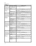
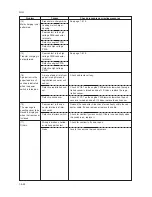
C4000
C4010
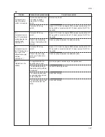
C6000
C6020
Polygon motor synchronization
problem
• The polygon motor does not reach
the stable speed within 15 s of the
START signal turning on.
Polygon motor steady-state problem
• The polygon motor rotation is not
stable for 5 s after the polygon motor
rotation has been stabilized.
Broken fusing heater wire
• In fusing warm-up, the time to reach
50
°
C/122
°
F exceeds 13.5 s, the
time to reach 100
°
C/212
°
F exceeds
10 s, the time to reach the primary
stabilization exceeds 10 s or the time
to reach the secondary stabilization
exceeds 24 s.
Abnormally high fusing unit ther-
mistor temperature
• The fusing temperature exceeds 230
°
C/446
°
F for 40 ms.
Poor contact in
the polygon motor
connector termi-
nals.
Defective polygon
motor.
Defective engine
PWB (KP-5238).
Poor contact in
the polygon motor
connector termi-
nals.
Defective polygon
motor.
Defective engine
PWB (KP-5238).
Poor contact in
the thermistor
connector termi-
nals.
Thermistor in-
stalled incorrectly.
Thermal cutout
triggered.
Heater lamp in-
stalled incorrectly.
Broken heater
lamp wire.
Shorted ther-
mistor.
Broken heater
control circuit on
the power supply
PWB.
Reinsert the connector. Also check for con-
tinuity within the connector cable. If none,
remedy or replace the cable.
Replace the LSU.
Replace the engine PWB and check for
correct operation.
Reinsert the connector. Also check for con-
tinuity within the connector cable. If none,
remedy or replace the cable.
Replace the LSU.
Replace the engine PWB and check for
correct operation.
Check the connection of connector YC4 on
the power supply PWB and the continuity
across the connector terminals. Repair or
replace if necessary.
Check and reinstall if necessary.
Check for continuity. If none, replace the
thermal cutout.
Check and reinstall if necessary.
Check for continuity. If none, replace the
heater lamp.
Measure the resistance. If it is 0
Ω
, replace
the thermistor.
Replace the power supply PWB and check
for correct operation.
Summary of Contents for CD 1018
Page 1: ...Service Manual MFP Copy CD 1018 Date 17 03 2005 ...
Page 2: ...Service Manual MFP Copy DC 2018 Date 17 03 2005 ...
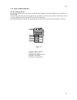
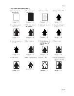
Page 70: ...2GM 1 5 2 2 Paper misfeed detection conditions Registration sensor Exit sensor Figure 1 5 2 ...
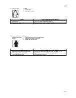
Page 124: ...2GM 1 6 31 Eraser lamp 9 Remove the eraser lamp Figure 1 6 35 Removing the eraser lamp ...


