background image

2GM

1-4-15

Maintenance

Description

item No.

U425

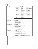
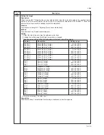
Setting the target

Description

When running U411 “Adjusting the scanner automatically,” input the color data value of the specified patch
written in the LAB value table on the back side of the original for adjustment (P/N: 2A668011). Note that
incorrect value input results in improper automatic adjustment.

Purpose

To run before running U411 “Adjusting the scanner automatically.”

Method

Press the enter key. A selection item appears.

Setting

1. Select the item to be set using the up/down cursor keys.
2. Change the setting using the left/right cursor keys or keypad.

* Input the values written in the LAB value table on the back side of the original.

Display

Description

Setting range

N8.75(L*)

Black N8.75 (L*) target

      0.0 to +100.0

N8.75(a*)

Black N8.75 (a*) target

–200.0 to +200.0

N8.75(b*)

Black N8.75 (b*) target

–200.0 to +200.0

N4.75(L*)

Black N4.75 (L*) target

      0.0 to +100.0

N4.75(a*)

Black N4.75 (a*) target

–200.0 to +200.0

N4.75(b*)

Black N4.75 (b*) target

–200.0 to +200.0

N1.25(L*)

Black N1.25 (L*) target

      0.0 to +100.0

N1.25(a*)

Black N1.25 (a*) target

–200.0 to +200.0

N1.25(b*)

Black N1.25 (b*) target

–200.0 to +200.0

C(L*)

Cyan (L*) target

      0.0 to +100.0

C(a*)

Cyan (a*) target

–200.0 to +200.0

C(b*)

Cyan (b*) target

–200.0 to +200.0

M(L*)

Magenta (L*) target

      0.0 to +100.0

M(a*)

Magenta (a*) target

–200.0 to +200.0

M(b*)

Magenta (b*) target

–200.0 to +200.0

Y(L*)

Yellow (L*) target

      0.0 to +100.0

Y(a*)

Yellow (a*) target

–200.0 to +200.0

Y(b*)

Yellow (b*) target

–200.0 to +200.0

R(L*)

Red (L*) target

      0.0 to +100.0

R(a*)

Red (a*) target

–200.0 to +200.0

R(b*)

Red (b*) target

–200.0 to +200.0

G(L*)

Green (L*) target

      0.0 to +100.0

G(a*)

Green (a*) target

–200.0 to +200.0

G(b*)

Green (b*) target

–200.0 to +200.0

B(L*)

Blue (L*) target

      0.0 to +100.0

B(a*)

Blue (a*) target

–200.0 to +200.0

B(b*)

Blue (b*) target

–200.0 to +200.0

3. Press the enter key. The value is set.

Completion

Press the back key. The indication for selecting a maintenance item No. appears.

Summary of Contents for CD 1018

Page 1: ...Service Manual MFP Copy CD 1018 Date 17 03 2005 ...

Page 2: ...Service Manual MFP Copy DC 2018 Date 17 03 2005 ...

Page 3: ...osion if battery is incorrectly replaced Replace only with the same or equivalent type recommended by the manufacturer Dispose of used batteries according to the manufacturer s instructions CAUTION Double pole neutral fusing ...

Page 4: ...ompliance with warning messages using this symbol WARNING Serious bodily injury or death may result from insufficient attention to or incorrect compliance with warning messages using this symbol CAUTION Bodily injury or damage to property may result from insufficient attention to or incorrect compliance with warning messages using this symbol Symbols The triangle symbol indicates a warning includi...

Page 5: ...d or dusty place This may cause fire or electric shock Do not install the copier near a radiator heater other heat source or near flammable material This may cause fire Allow sufficient space around the copier to allow the ventilation grills to keep the machine as cool as possible Insufficient ventilation may cause heat buildup and poor copying performance Always handle the machine by the correct ...

Page 6: ...e clean Dirt on them can cause abnormally high temperatures Do not remove the ozone filter if any from the copier except for routine replacement 2 Precautions for Maintenance WARNING Always remove the power plug from the wall outlet before starting machine disassembly Always follow the procedures for maintenance described in the service manual and other related brochures Under no circumstances att...

Page 7: ...at all the caution labels that should be present on the machine according to the instruction handbook are clean and not peeling Replace with new ones if necessary Handle greases and solvents with care by following the instructions below Use only a small amount of solvent at a time being careful not to spill Wipe spills off completely Ventilate the room well while using grease or solvents Allow app...

Page 8: ...2 System settings 1 4 19 1 4 3 Service settings 1 4 21 1 Executing a service setting item 1 4 21 2 Contents of service setting items 1 4 22 1 5 Troubleshooting 1 5 1 Paper misfeed detection 1 5 1 1 Paper misfeed indication 1 5 1 2 Paper misfeed detection conditions 1 5 2 3 Paper misfeeds 1 5 4 1 5 2 Self diagnosis 1 5 8 1 Self diagnostic function 1 5 8 2 Self diagnostic codes 1 5 8 1 5 3 Image for...

Page 9: ...aper feed 1 5 25 3 Skewed paper feed 1 5 25 4 The scanner does not travel 1 5 25 5 Multiple sheets of paper are fed at one time 1 5 25 6 Paper jams 1 5 25 7 Abnormal noise is heard 1 5 25 1 6 Assembly and Disassembly 1 6 1 Precautions for assembly and disassembly 1 6 1 1 Precautions 1 6 1 1 6 2 Removing the process unit 1 6 2 1 6 3 Removing the principal outer covers 1 6 3 1 Removing the front top...

Page 10: ...enter line 1 6 52 13 Adjusting the margins for scanning the original from the DP 1 6 53 1 7 Upgrading the firmware 1 7 1 Upgrading the firmware on the main PWB 1 7 1 2 1 Mechanical construction 2 1 1 Paper feeding system 2 1 1 1 Paper feed control 2 1 2 2 Paper feeding mechanism 2 1 3 2 1 2 Original scanning system 2 1 4 1 ISU unit 2 1 6 2 1 3 Electrophotographic system 2 1 7 1 Electrophotographic...

Page 11: ...1 1 4 2GM 2 3 6 CCD PWB 2 3 22 2 3 7 Operation PWB 2 3 24 2 3 8 Scanner PWB 2 3 26 2 4 Appendixes Timing chart No 1 2 4 1 Timing chart No 2 2 4 2 Timing chart No 3 2 4 3 Wiring diagram 2 4 4 ...

Page 12: ...120 g m2 10 sheets 160 g m2 1 sheet Transparency Stacking capacity Output tray Approx 150 sheets 80 g m2 Face up tray 30 sheets 80 g m2 1 sheet Special paper Standard memory 96 MB 64 MB of system memory and 32 MB of additional memory Approx 70 pages of memory possible with letter size 5 Text Photo mode Additional memory 1 slot 64 MB 128 MB or 256 MB Continuous copying 1 999 sheets Scanning system ...

Page 13: ...Q 850 PCL6 and KPDL Scanning functions Scanning speed Monochrome 18 spm Full color or Grayscale 4 8 spm 1 1 A4 81 2 11 200 dpi Resolution 200 100 200 400 200 300 400 and 600 dpi Color mode Full color Grayscale and Monochrome Halftone Full color 8 bit dot each color Grayscale 8 bit dot Monochrome 1 bit dot Original quality mode Text Photo Photo Text and OCR File format PDF All modes TIFF only monoc...

Page 14: ...nit 8 Toner container 9 Lock lever 0 Toner container release lever Main charger cleaner Cassette Paper guide Paper stopper 2 fi fl 1 3 5 6 7 8 9 0 4 Stopper extension lock Face down output tray MP tray Extension tray Paper width guides Power switch Face up output tray Power cord DP interface connector Memory cover fi Parallel interface connector fl USB interface connector Network interface connector ...

Page 15: ...eive indicator Memory indicator Error indicator System menu Counter key and indicator Log out key and indicator Numeric keys Reset Power key Figure 1 1 2 Main power indicator Original quality key and indicator Original size key and indicator Exposure key and indicator Paper select key and indicator Message display Left select key Right select key fi Back key fl Left cursor key Up cursor key Down cur...

Page 16: ...Ensure that the photoconductor will not be exposed to direct sunlight or other strong light when removing paper jams Avoid extremes of temperature and humidity abrupt ambient temperature changes and hot or cold air directed onto the machine Avoid dust and vibration Choose a surface capable of supporting the weight of the machine Place the machine on a level surface maximum allowance inclination 1 ...

Page 17: ...llation procedure Unpack Inisializing the machine Connect the power cord Load paper Using the one touch key sheet Make test copies Start Remove the pin holding scanner unit Install a toner container Remove the tapes pads and sheets End of installation ...

Page 18: ... pad 9 Upper pad 0 Side pad Figure 1 3 1 Unpacking Front spacer Front pad Bottom spacer Cassette spacer Left pad Right pad Corner supports Products cover Plastic bag Plastic bag 0 fi fl fi 3 9 5 4 6 2 fl 8 1 7 Pocket spacer Paper tag Top sheet Output tray sheet fi Bar code labels fl Label Operation guide Installation guide Plastic bag ...

Page 19: ...e sure not to pull the cassette out when holding the front of the machine Be sure that the original cover is closed whenever transporting the machine Do not attempt to carry the machine by holding only the top portion Doing so may result in you dropping the machine and thereby damaging the machine and or its covers Figure 1 3 2 ...

Page 20: ...1 3 4 2GM 1 Remove the sheet and the two tapes 2 Open the original cover Remove the tapes pads and sheets Figure 1 3 3 Figure 1 3 4 Tapes Sheet Original cover ...

Page 21: ...ht tapes the two pads and the sheet 4 Pull the cassette out of the machine 5 Remove the cassette spacer from inside the cassette Figure 1 3 5 Figure 1 3 7 Figure 1 3 6 Tape Tape Cassette Cassette spacer Tapes Tapes Sheet Pad Pad ...

Page 22: ...and front cover 2 Store the pin for scanner unit on the inside of the front cover as shown in the illustration Be sure to save this pin as it is essential that it be used whenever the machine is moved The location for storing the pin is clearly marked on the right side of the inside portion of the front cover Install a toner container Front top cover Front cover Figure 1 3 9 Pin Figure 1 3 10 ...

Page 23: ... of impact or shock The drum in the process unit is sensitive to light Never expose the drum even to normal office lighting 500 lux for more than five minutes 4 Remove the protective cardboard 5 Move the lock lever until it is in its unlocked position marked UNLOCK Figure 1 3 11 Figure 1 3 13 Figure 1 3 12 Process unit Protective cardboard Lock lever ...

Page 24: ...ide of it becomes evenly distributed 7 Remove the orange protective seal 8 Align the knob on the left side of the container with the groove in the process unit and set the toner container into the process unit Figure 1 3 14 Figure 1 3 16 Figure 1 3 15 Toner container Seal Process unit Knob Toner container ...

Page 25: ... 10 Push the lock lever back into its locked position 11 Set the process unit into the machine by aligning the pins on both sides of the process unit with the guides inside the machine and then slide the process unit all the way back into the machine until it stops Figure 1 3 17 Figure 1 3 19 Figure 1 3 18 Toner container Lock lever Pin Pin ...

Page 26: ...1 3 10 2GM 12 Close the front cover 13 Close the front top cover Figure 1 3 20 Figure 1 3 21 Front cover Front top cover ...

Page 27: ...d 1 Turn the power switch to the machine ON The machine will begin replenishing the toner Wait until it has completed that operation 15 minutes Once the toner has been replenished and the machine is once again in a ready to use state Ready to copy will appear on the message display and the Start indicator will light green Power switch ...

Page 28: ...t factory setting is for A4 Letter size paper Adjusting the paper stopper for Folio or Oficio II size paper 1 Remove the stopper extension lock from the paper stopper 2 Slide the paper stopper towards the rear of the cassette until the grooves that are cut into the paper stopper are aligned with the rear edge of the cassette 3 Insert the stopper extension lock into the holes in the paper stopper a...

Page 29: ...sliding the guides to fit the width of the paper being loaded in the cassette NOTES The paper sizes are marked on the bottom of the cassette The default setting is for A4 Letter size paper 4 Set the paper in the cassette so that the leading edge is aligned against the paper stopper but making sure that none of the paper gets caught on the overhanging tabs Paper stopper Stopper extension lock Figur...

Page 30: ... any gap between the paper and the stopper or guides readjust the paper stopper and or the paper width guides as appropriate When you are loading paper into the cassette make sure that the side to be copied or printed onto is facing downward Be sure to load paper so that it is not folded or curled etc Do not load more paper than indicated by the lines located on the width guides 5 Push the cassett...

Page 31: ...ation panel 2 Enter the information for the registered destinations onto the one touch key sheet There are 4 spare one touch key sheets included with this machine 3 Insert the sheet back between the one touch keys from the bottom side of the operation panel One touch key sheet Figure 1 3 33 H G F E D C B A One touch key sheet Figure 1 3 34 ...

Page 32: ...Procedure 1 Turn the power switch located on the rear side of the machine off O and remove the power cord from the outlet 2 Connect the network cable to the network connector at the rear side of the machine 3 Connect the other end of the network cable to network device hub 4 Make network settings Figure 1 3 35 Figure 1 3 36 Power switch Network cable ...

Page 33: ...off O remove the power cord from the outlet and turn the power off to computer 2 Connect the printer cable to the parallel interface connector or USB interface connector located at the rear side of the machine 3 Connect the other end of the printer cable to the parallel interface connector or USB interface connector on computer Power switch Printer cable USB interface connector Figure 1 3 37 Figur...

Page 34: ... it as shown in the illustration Be particularly careful NOT to touch the guide film or the thin white surface indicated by the A in the illustration 2 Turn the power switch located on the rear side of the machine off O Disconnect the power cord 3 Open the original cover and lift it upward to remove it from the machine Figure 1 3 39 Figure 1 3 40 A Document processor Power switch Oringinal holder ...

Page 35: ...connection cable does not get caught between the document processor and the machine when attaching the document processor to the machine 5 Gently close the document processor 6 Attached the open end of the connection cable to the connector on the machine Connection cable Document processor Connection cable Document processor ...

Page 36: ... to tighten the pins securely when connecting the cable 7 Connect the power cord and turn the power switch on Warm up will begin 1 will appear on the operation panel and the start indicator will light when the machine is in a ready state Pins Power switch ...

Page 37: ...ess Operation of the machine during the presence of a foreign substance may lead to fire or electric shock WARNING Turn the power switch off Disconnect the power cord Procedure 1 Remove the screw and then remove the memory cover 3 Open the clips on both ends of the DIMM socket 4 Insert the DIMM into the DIMM socket so that the notches on the DIMM align with the corresponding protrusions in the slo...

Page 38: ... electricity before removing the FAX assembly from the bag Hold the FAX assembly by the metal plate on front as shown Do not touch the circuits or electronic components on the PWB Plate Screw Screw Figure 1 3 49 Procedure 1 On the rear of the machine remove two screws and then remove the plate Plate Screw Screw Figure 1 3 50 2 Insert the FAX assembly along the rail in the machine until it clicks i...

Page 39: ...ns only 4 Attach the core to the power cord of the machine so that the stopper section is located near the power plug as shown in the illustration Figure 1 3 53 5 Plug the power cord into the machine Turn the machine on NOTE 120 V specifications only When connecting a separate phone to the machine attach the ferrite core to the modular cord before connection Loop the modular cord through the ferri...

Page 40: ...6 137 152 156 South Africa Thailand U S A South America Saudi Arabia CTR21 European nations Italy Germany Spain U K Netherlands 159 169 181 242 243 253 Code Code Destination Destination Destination Sweden France Austria Switzerland Belgium Denmark Finland Portugal Ireland Norway Taiwan 253 254 4 Enter the OEM code 000 and then press the enter key 5 After data initialization the entered destination...

Page 41: ...intenance item Run another maintenance item Turning power switch off and back on No No Yes Yes Select Maintenance mode using the up down cursor keys Enter the maintenance item number using the up down keys While pressing the start key and the key press the enter key Press the system menu counter key Press the enter key The test print mode cannot be stopped until the preset number of sheets is prin...

Page 42: ...087 Turning the DP scanning position adjust mode on off 35 U089 Outputting a MIP PG pattern U101 Setting the other high voltages 26 55 48 43 24 60 U130 Initial setting for the developer OFF U144 Setting toner loading operation 1 U157 Checking clearing the developing drive time U161 Setting the fusing control temperature Primary stabilization fusing temperature 135 Secondary stabilization fusing te...

Page 43: ...ing the backup RAM output a list of the current settings of the maintenance items to reenter the settings after initialization or replacement Method 1 Press the enter key A selection item appears 2 Select the item to be output using the up down cursor keys Display Output list Maintenance Outputs the maintenance list Event Log Outputs the event log report 3 Press the enter key The test print mode i...

Page 44: ...05 Secondary paper feed timeout H 10 No paper feed from the MP tray B 11 No paper feed from the cassette C 12 No paper feed from the optional cassette D 20 Multiple sheets in the MP tray B 21 Multiple sheets in the cassette C 22 Multiple sheets in the optional cassette D 40 Misfeed in the fusing section H 50 Misfeed in the exit section G 70 No original feed P 71 An original jam in the original con...

Page 45: ...put tray 2 Service Call Log Log number 1 to 8 service calls are recorded If the number of service calls exceeds 8 the oldest log is deleted Count Number of pages Total page counter at the time of service call Service code Log code 3 Maintenance Log Log number 1 to 8 maintenance logs are recorded If the number of replacement times exceeds 8 the oldest log is deleted Count Number of pages Total page...

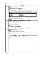
Page 46: ...ount of slack in the paper Adjustment See page 1 6 43 U060 Adjusting the scanner input properties Description Adjusts the image scanning density Purpose Used when the entire image appears too dark or light Method Press the enter key Setting 1 Change the setting using the left right cursor keys Display Description Setting range Initial setting γ Adj MONO Image scanning density 0 to 23 12 Increasing...

Page 47: ... print mode While this maintenance item is being performed copying from an original can be made in test print mode 1 Press the system menu counter key The machine enters the test print mode 2 Set the original and press the start key The test printing however cannot be stopped until the preset number of sheets is printed 3 To return to the indication for setting press the system menu counter key Co...

Page 48: ... Turns on or off the DP scanning position adjust mode in which the DP original scanning position is adjusted automatically by determining the presence or absence of dust on the slit glass Also changes the reference data for identifying dust Reference In the DP original scanning position adjust mode the presence or absence of dust is determined by comparing the scan data of the original trailing ed...

Page 49: ...elect whether output of γ is on or off Display Description γ Off Output of γ off γ On Output of γ on 4 Press the enter key 5 Press the system menu counter key The machine enters the PG pattern output mode 6 Press the start key A MIP PG pattern is output 7 To return to the indication for setting press the system menu counter key Method Monochrome PG output 1 Change the setting using the left right ...

Page 50: ...eys 2 Change the setting using the left right cursor keys Display Description Setting range Initial setting DB_100Hz CPY Developing bias clock frequency 2 to 255 26 DB_Duty CPY Developing bias clock frequency 1 to 99 55 TC Off 10ms Transfer charging output OFF timing 0 to 255 48 TC On 10ms Transfer charging output ON timing 0 to 255 43 DB_100Hz PRT Developing bias clock frequency 2 to 255 24 DB_Du...

Page 51: ...intenance item No appears U157 Checking clearing the developing drive time Description Displays the developing drive time for checking or changing a figure Purpose To enter the developing drive time again after carrying out initialization with U020 and to clear the developing drive time when replacing process unit Method 1 Press the enter key The developing drive time is displayed in minutes 2 Cha...

Page 52: ...tion after the specified number of sheets for fusing control have passed Number of sheets for fusing control The number of sheets to be counted for switching from printing operation temperature 1 to printing operation temperature 2 The temperatures are to be set such that Secondary stabilization Primary stabilization 3 Press the enter key The value is set Completion Press the back key The indicati...

Page 53: ...ure shown increases in increments of 1 If there is an LED corresponding to the key pressed the LED will light 4 When all keys are pressed all LEDs will light for 10 s Completion Press the stop clear key The indication for selecting a maintenance item No appears U260 Changing the copy count timing Description Changes the copy count timing for the total counter and other counters Purpose To be set a...

Page 54: ...te Before carrying out automatic adjustment input the target values using U425 Setting the target Method 1 Run U425 Setting the target to input the target values 2 Set the original to be used for adjustment on the platen 3 Set five or six sheets of blank paper on the original for adjustment that has been set 4 Press the enter key A selection item appears 5 Select Execute using the up down cursor k...

Page 55: ...k N8 75 b target 200 0 to 200 0 N4 75 L Black N4 75 L target 0 0 to 100 0 N4 75 a Black N4 75 a target 200 0 to 200 0 N4 75 b Black N4 75 b target 200 0 to 200 0 N1 25 L Black N1 25 L target 0 0 to 100 0 N1 25 a Black N1 25 a target 200 0 to 200 0 N1 25 b Black N1 25 b target 200 0 to 200 0 C L Cyan L target 0 0 to 100 0 C a Cyan a target 200 0 to 200 0 C b Cyan b target 200 0 to 200 0 M L Magenta...

Page 56: ...lecting a maintenance item No appears U905 Checking clearing counts by the DP Description Displays the counts of the DP Purpose To check the use of the optional DP Method Press the enter key The count will be displayed To clear the count press the enter key Completion Press the back key The indication for selecting a maintenance item No appears U911 Checking clearing print counts by paper size Des...

Page 57: ...ss the enter key A selection item appears 2 Select Execute using the up down cursor keys If the counter has been cleared Execute is not displayed 3 Press the enter key The accounting counter is cleared Completion Press the back key The indication for selecting a maintenance item No appears U928 Checking the machine life count Description Displays the machine life count for checking a figure Purpos...

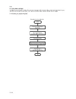
Page 58: ...nly by the machine administrator In this machine system settings default settings can be changed 1 Executing a system setting item Press the System Menu Counter key Start Executing a system setting item Select an setting item using the up down cursor keys Press the enter key Select the Exit using the right select key End Execute the system setting item ...

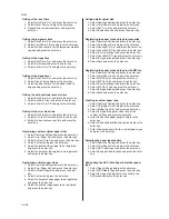
Page 59: ...y 2 Select the default setting and press the enter key 3 Select the new default setting and press the enter key Registering destination E mail addresses under one touch keys 1 Select Common Setting and press the enter key 2 Select One Touch Keys and press the enter key 3 Select the number of the one touch and press the enter key 4 Select E mail and press the enter key 5 Enter or revise the e mail ...

Page 60: ... be registered and press the enter key Setting defalt original size 1 Select Common Setting and press the enter key 2 Select Orig Paper Set and press the enter key 3 Select Def Org Size and press the enter key 4 Select the desired size and press the enter key Registering the paper size and type for cassettes 1 Select Common Setting and press the enter key 2 Select Orig Paper Set and press the ente...

Page 61: ...ecuting a service setting item Press the System Menu Counter key Start Executing a system setting item Select Service Setting using the up down cursor keys Select an setting item using the up down cursor keys Press the enter key Select the Exit using the right select key End Execute the system setting item Press the enter key ...

Page 62: ...OM Version Front Panel ROM Version NVRAM Version Scanner Version Serial No MAC Address Toner Coverage Average Last Page Size Conversion Counter Printed Total Printed Pages Copier Printer FAX Scanned Total Scanned Pages Copier Other Paper Size FAX information Rings Normal Rings FAX TEL Rings TAD TX SPEED RX SPEED ECM TX ECM RX V 34 REG G3 TX EQR REG G3 RX EQR RX MODEM LEVEL SGL LVL MODEM 1 1 478 57...

Page 63: ...gain odd result Monochirome AGC gain odd setting value Monochirome AGC gain even result Monochirome AGC gain even setting value Color AGC offset red result Color AGC offset red setting value Color AGC offset green result Color AGC offset green setting value Color AGC offset blue result Color AGC offset blue setting value Color AGC gain red result Color AGC gain red setting value Color AGC gain gre...

Page 64: ...1 Drawer counter most significant byte 32 secod byte 33 third byte 34 least significant byte 35 Optional drawer counter most significant byte 36 secod byte 37 third byte 38 least significant byte 39 DP counter most significant byte 40 secod byte 41 third byte 42 least significant byte 43 Paper size counter A4 size most significant byte 44 secod byte 45 third byte 46 least significant byte 47 B5 si...

Page 65: ...significant byte 68 secod byte 69 third byte 70 least significant byte 71 51 2 81 2 size most significant byte 72 secod byte 73 third byte 74 least significant byte 75 Other size most significant byte 76 secod byte 77 third byte 78 least significant byte 79 Machine life counter most significant byte 80 secod byte 81 third byte 82 least significant byte ...

Page 66: ...ap Community Trap IP Address Trap IPX Address Add Paper Low Toner Add Toner Cover Open Paper Jam All Other Errors Network Status 1 POP3 Status Check Interval User 1 User Profile1 POP Port Number POP Server Name POP3 Login Account Name POP3 Login Password Use APOP Delete Mail After Retrieval Mail Size Limit SMTP Status SMTP Server Name SMTP Port Number Authentication Login Account Name Sender Addre...

Page 67: ...ode is useful when dew condensation on the drum occurs Procedure 1 Select Drum Refresh using cursor up down keys and press the enter key 2 Select Yes using the left select key Drum surface refreshing will start and finish after approximately 2 minutes Transport mode Description Follow the instructions below to reinstall the transport pin before moving the machine Procedure 1 Select Transport mode ...

Page 68: ...chine Description Set to take advantage of our remote diagnosis system Procedure 1 Select Remote Diag Set using up down cursor keys and press the enter key 2 Select Off or On using the up down cursor keys and press the enter key Entering the FAX remote ID number Note This setting is only available when the optional fax system is installed in the machine Description Register the designated remote t...

Page 69: ...open the face up output tray front top cover front cover or pull the cassette out To remove original jammed in the optional DP open the DP original cover Paper misfeed detection can be reset by opening and closing the respective covers to turn interlock switch off and on Figure 1 5 1 1 Misfeed inside the machine 2 Misfeed in the cassette 3 Misfeed in the optional cassette 4 Misfeed in the MP tray ...

Page 70: ...2GM 1 5 2 2 Paper misfeed detection conditions Registration sensor Exit sensor Figure 1 5 2 ...

Page 71: ...ration sensor does not turn on within 1160 ms of the feed clutch turning on the clutch is then successively turned off for 1 s and turned back on once but the sensor again fails to turn on within 1160 ms The registration sensor does not turn off within 5055 ms of the registration clutch turning on when paper is fed from the MP tray The registration sensor does not turn off within 5055 ms of the re...

Page 72: ...ctrical problem with the feed clutch Paper in the optional cas sette is extremely curled Check if the feed roller of the optional cassette is deformed Defective registration sen sor Check if the feed clutch malfunctions Electrical problem with the feed clutch Check visually and remove it if any Check if YC8 7 on the engine PWB remains low when the regis tration sensor is turned on and off If it do...

Page 73: ...heck if the registration clutch malfunctions Electrical problem with the registration clutch Check if the upper and lower registration rollers contact each other Check if the lower exit roller and exit pulleys con tact each other Check if the press roller is extremely dirty or de formed Check if the separators are dirty or deformed Check visually and replace any deformed roller Check if YC8 7 on t...

Page 74: ... roller and exit pulleys con tact each other Check if the upper exit roller and exit pulleys con tact each other Check if YC8 7 on the engine PWB remains low when the regis tration sensor is turned on and off If it does replace the regis tration sensor Check if YC7 7 on the engine PWB remains low when the exit sensor is turned on and off If it does replace the exit sensor Check visually and remedy...

Page 75: ...ications is used The forwarding pulley or feed pulley is dirty with pa per powder The conveying roller and conveying pulleys do not contact correctly The exit roller and exit pul leys do not contact cor rectly Remove any found Check if YC10 6 on the engine PWB remains low when the DP timing switch is turned on and off If it does replace the DP tim ing switch Check if YC10 6 on the engine PWB remai...

Page 76: ...B Problem with the backup memory data Defective backup RAM Defective main PWB or engine PWB Defective main PWB or engine PWB Poor contact in the connector ter minals Defective main PWB or engine PWB Replace the fax control PWB and check for correct operation Check the version of the Fax software and the main software upgrade the version to the compatible software Replace the engine PWB and check f...

Page 77: ...the optional fax control PWB Poor contact in the connector ter minals Defective main PWB or operation PWB Poor contact in the connector ter minals Defective main PWB or fax con trol PWB Defective engine PWB Defective fax con trol PWB Poor contact in the connector ter minals Defective fax con trol PWB or main PWB Defective fax con trol PWB Defective fax con trol PWB Check the connection of connecto...

Page 78: ... lamp or in verter PWB Incorrect shading position Poor contact of the connector ter minals Reinsert the connector Also check for con tinuity within the connector cable If none remedy or replace the cable Replace the main motor Check if the rollers and gears rotate smoothly If not grease the bushings and gears Check for broken gears and replace if any Check the connection of connectors YC10 11 on t...

Page 79: ...ve polygon motor Defective engine PWB KP 5238 Poor contact in the thermistor connector termi nals Thermistor in stalled incorrectly Thermal cutout triggered Heater lamp in stalled incorrectly Broken heater lamp wire Shorted ther mistor Broken heater control circuit on the power supply PWB Reinsert the connector Also check for con tinuity within the connector cable If none remedy or replace the cab...

Page 80: ...place the cable Replace the operation PWB and check for correct operation Reinsert the connector Also check for con tinuity within the connector cable If none remedy or replace the cable Replace the operation PWB and check for correct operation C6050 C6400 C7800 C7810 Abnormally low fusing unit ther mistor temperature The fusing temperature remains be low 90 C 194 F for 1 s Zero crossing signal pr...

Page 81: ...switch off and then on If the problem cannot be solved replace the process unit After replacing the process unit turn the power switch off and then on If the prob lem cannot be solved replace the waste toner sensor or the engine PWB Shake the process unit from side to side and turn the power switch off and then on If the problem cannot be solved replace the process unit After replacing the process...

Page 82: ...ven after the power switch is turned off and then on again contact the Service Administrative Division If this error occurs again even after the power switch is turned off and then on again contact the Service Administrative Division If this error occurs again even after the power switch is turned off and then on again contact the Service Administrative Division If this error occurs again even aft...

Page 83: ... 1 5 18 7 A black line appears laterally See page 1 5 18 8 One side of the print image is darker than the other See page 1 5 18 9 Black dots appear on the image See page 1 5 19 10 Image is blurred See page 1 5 19 11 The leading edge of the image is consistently misaligned with the original See page 1 5 19 12 Paper creases See page 1 5 20 13 Offset occurs See page 1 5 20 14 Image is partly missing ...

Page 84: ...or contact D Defective engine PWB E Defective high voltage PWB 2 Exposure lamp fails to light A The connector terminals of the exposure lamp make poor contact B Defective CCD PWB C Defective scanner PWB D Defective engine PWB 2 No image appears entirely black Causes 1 No main charging 2 Exposure lamp fails to light Replace the process unit Replace the process unit Reinsert the connector Also check...

Page 85: ...ckground is visible Causes 1 Insufficient toner 2 Deteriorated developer 3 Dirty or deteriorated drum Causes Check procedures corrective measures 1 Insufficient toner 2 Deteriorated developer 3 Dirty or deteriorated drum Causes 1 Deteriorated developer Causes Check procedures corrective measures 1 Deteriorated developer Replace the process unit If the add toner indicator lights replace the toner c...

Page 86: ...ures corrective measures 1 Dirty main charger wire 2 Defective exposure lamp Causes Check procedures corrective measures 1 Flawed drum 2 Dirty developing section 3 Leaking main charger housing 7 A black line ap pears laterally Causes 1 Flawed drum 2 Dirty developing section 3 Leaking main charger housing 8 One side of the print image is darker than the other Causes 1 Dirty main charger wire 2 Defe...

Page 87: ...3 Deformed or worn cleaning blade Causes Check procedures corrective measures 1 Dirty or flawed drum 2 Dirty contact glass 3 Deformed or worn cleaning blade Causes 1 Deformed press roller 2 Paper conveying section drive problem Causes Check procedures corrective measures 1 Deformed press roller 2 Paper conveying section drive problem Replace the press roller see page 1 6 26 Check the gears and bel...

Page 88: ... Replace the paper 3 Flawed drum Replace the process unit 13 Offset occurs 12 Paper creases Causes 1 Paper curled 2 Paper damp Causes Check procedures corrective measures 1 Paper curled Check the paper storage conditions 2 Paper damp Check the paper storage conditions Causes 1 Defective cleaning blade Causes Check procedures corrective measures 1 Defective cleaning blade Replace the process unit ...

Page 89: ... procedures corrective measures 1 Misadjusted center line of image printing Readjust the center line of image printing see page 1 6 42 2 Misadjusted scanner center line Readjust the scanner center line see page 1 6 47 3 Original placed incorrectly Place the original correctly 16 Image center does not align with the original center Causes 1 Misadjusted center line of image printing 2 Misadjusted sc...

Page 90: ...ts If none replace the power switch Check for continuity If none remove the cause of blowing and replace the fuse Check for continuity across the contacts of switch If none re place the switch With AC present check for 24 V DC at YC2 6 and 5 V DC at YC2 1 on the power supply PWB If none replace the power supply PWB Reinsert the connector Also check for continuity within the con nector cable If non...

Page 91: ... for continuity across the coil If none replace the registra tion clutch Reinsert the connector Also check for continuity within the con nector cable If none remedy or replace the cable Check if YC6 2 on the engine PWB goes low when the registra tion clutch is turned on If not replace the engine PWB Reinsert the connector Also check for continuity within the con nector cable If none remedy or repl...

Page 92: ...ht around registration sensor or exit sensor Defective registration sen sor Defective exit sensor Poor contact in the con nector terminals of inter lock switch Defective interlock switch Wiring is broken shorted or makes poor contact Noise See page 1 5 16 See page 1 5 16 Check and remove if any Check if YC8 7 on the engine PWB remains low when the regis tration sensor is turned on and off If it do...

Page 93: ...r and MP feed roller are dirty with paper powder Check if the feed roller and MP feed roller are deformed Electrical problem with the feed clutch and MP feed clutch Check if the surfaces of the upper and lower registration rollers are dirty with paper pow der Electrical problem with the registration clutch Deformed width guide in a cassette The scanner motor malfunctions Deformed cassette claw Che...

Page 94: ...s or damage the board Do not touch any PWB containing ICs with bare hands or any object prone to static charge Use only the specified parts to replace the fuser unit thermostat Never substitute electric wires as the machine may be seriously damaged Do not perform aging without the waste toner tank installed during maintenance service Prepare the following as test originals 1 NTC new test chart 2 N...

Page 95: ...not place floppy disks near the process unit If the process unit is replaced for some reason the toner installation mode must be run 1 Run maintenance mode U157 to clear the developing drive time 2 Run maintenance mode U130 to turn the setting ON 3 Turn the power switch off and then on again The toner installation mode starts to add toner to the developing section of the process unit approximately...

Page 96: ...w and then remove the rear cover Figure 1 6 2 Removing the memory cover and rear cover 3 While unlatching the two latches and then remove the front top cover face down output tray Latches Front top cover face down output tray front top cover face down output tray Screw Screw Screw Screw Rear cover Memory cover Figure 1 6 3 Removing the front top cover face down output tray ...

Page 97: ... 3 3 Unlatch the snaps and hook remove the right cover Figure 1 6 4 Removing the right cover 3 Removing the left cover 1 Remove the front top cover face down output tray see page1 6 3 2 Unlatch the snaps and hooks remove the left cover Figure 1 6 5 Removing the left cover Left cover Left cover Right cover Right cover Snap Hook inside cover ...

Page 98: ...fit the D cut shaft into the D shape hole of the feed roller 1 Remove the cassette and the process unit see page 1 6 2 2 Stand the machine the front side up 3 Move the feed roller in the direction A and remove the feed roller Figure 1 6 6 Removing the feed roller A Feed roller ...

Page 99: ...ed roller 1 Remove the engine PWB see page 1 6 9 2 Remove the screw 3 Remove the grounding plate 4 Remove the stop ring 5 Remove the MP feed clutch Figure 1 6 7 Removing the MP feed clutch Screw Grounding plate Stop ring MP feed clutch ...

Page 100: ...e pressing the latch by using the driver and then remove the MP feed unit Figure 1 6 8 Removing the MP feed unit 10 Remove the stop ring and then remove the MP feed roller Latch Screw Toner sensor Spring Screw Screw MP feed unit Figure 1 6 9 Removing the MP feed roller MP feed roller Stop ring ...

Page 101: ...rings make sure to refit the black colored bush and spring on the left side Also observe the correct direction to which the bush is fit in reference to the paper passing direction 1 Remove the process unit see page 1 6 2 2 Remove the transfer roller from the both bushes Figure 1 6 10 Removing the transfer roller Long Short Paper passing direction Transfer roller Bush Bush Black colored Spring Blac...

Page 102: ...e right cover see page 1 6 4 2 Remove all twelve connectors from the engine PWB 3 Remove three screws 4 Remove the engine PWB When replacing the PWB with a new PWB remove the EEPROM from the old PWB and mount it to the new PWB Figure 1 6 11 Removing the engine PWB Screws Engine PWB EEPROM ...

Page 103: ...er Figure 1 6 13 Removing the main controller shield with main PWB Connectors Main controller shield with main PWB Flexible flat cable Screw Screws 4 Remove three connectors 5 Remove the flexible flat cable 6 Remove seven screws and then remove the main controller shield with main PWB Figure 1 6 12 Removing the speaker Screw Speaker Connector ...

Page 104: ...11 7 Remove two screws at the back of the main PWB When replacing the PWB with a new PWB remove the EEPROM from the old PWB and mount it to the new PWB Figure 1 6 14 Removing the main PWB Screws Main PWB EEPROM ...

Page 105: ...nnectors from the power supply PWB 4 Remove eight screws 5 Remove the power supply PWB and high voltage PWB Note The high voltage PWB is directly connected to the bias PWB 6 Separate the high voltage PWB from the power supply PWB Figure 1 6 15 Removing the power supply PWB and high voltage PWB Screws Screws Connectors Power supply PWB High voltage PWB Bias PWB ...

Page 106: ... power supply PWB and high voltage PWB see page 1 6 12 4 Stand the machine with the front side up 5 Remove the connector from the bias PWB 6 Remove five screws 7 Remove the bottom cover 8 Remove two connectors from the bias PWB 9 Remove the bias PWB Figure 1 6 16 Removing the bias PWB Connector Connectors Bottom cover Bias PWB Screws Screws ...

Page 107: ...t 1 Remove the cassette and process unit see page 1 6 2 2 Remove the right cover see page 1 6 4 3 Remove three connectors from the main motor 4 Remove four screws 5 Remove main motor Figure 1 6 17 Removing the main motor Main motor Screws Screws Connectors ...

Page 108: ...6 Remove the engine PWB see page 1 6 9 7 Remove wires from wire saddles on the cord cover 8 Remove the screw 9 Remove the cord cover Figure 1 6 18 Removing the cord cover Wire saddles Wire saddle Cord cover Screw ...

Page 109: ...ve the screw and then remove the feed clutch 13 Remove three stop rings 14 Remove MP feed clutch gear feed clutch gear and registration clutch gear Figure 1 6 19 Removing the clutches Stop ring Stop ring Stop ring MP feed clutch gear Feed clutch gear Feed clutch Registration clutch gear Screw Screw Grounding plate ...

Page 110: ...2GM 1 6 17 15 Remove four screws 16 Remove the drive unit Figure 1 6 20 Removing the drive unit Screws Drive unit ...

Page 111: ...sure the fuser unit gear and the machine s drive gear are properly meshed with each other For this rotate the main motor several turns before fusing screws 1 Remove the rear cover see page 1 6 3 2 Remove the right and left cover see page 1 6 4 3 Remove two connectors 4 Remove two screws 5 Remove the fuser unit Figure 1 6 21 Removing the fuser unit Screws Screws Fuser unit Connectors ...

Page 112: ...2GM 1 6 19 6 Remove two screws 7 Open and split the fuser unit Figure 1 6 22 Splitting the fuser unit Screw Screw Fuser unit ...

Page 113: ...stantial period of time until it cools down 1 Remove and split the fuser unit see page 1 6 18 2 Loosen the stopper screws 3 Hold the separation claw upright and remove the separation claw and separation claw springs Figure 1 6 23 Removing the separation claws Step 1 Step 2 Separation claw Separation claw Separation claw spring Stopper screw ...

Page 114: ...s outer surface can prevent proper fusing of toner on paper When refitting the heater lamp direct the short distance side from the projection in the middle of the lamp facing the machine s left side 1 Remove and split the fuser unit see page 1 6 18 2 Remove all four separation claws see page 1 6 20 3 Remove the screw release the tension of the lamp A holder 4 Remove the heater lamp form the lamp B...

Page 115: ...ntial period of time until it cools down 1 Remove and split the fuser unit see page 1 6 18 2 Remove the heater lamp see page 1 6 22 3 Press the lamp A holder away from the heat roller Pull up both heat R bush and heat L bush at the same time Figure 1 6 25 Removing the heat R bush and heat L bush Lamp A holder Heat R bush Heat L bush ...

Page 116: ...2GM 1 6 23 4 Remove the heat gear Z33 heat R bush and heat L bush from the heat roller Figure 1 6 26 Removing the heat roller Heat gear Z33 Heat R bush Heat L bush Heat roller ...

Page 117: ...stor 1 Remove and split the fuser unit see page 1 6 18 2 Remove the heater lamp see page 1 6 21 3 Remove the heat roller see page 1 6 22 4 Remove the screw 5 Remove the thermistor Figure 1 6 27 Removing the thermistor Screw Thermistor ...

Page 118: ...inals of the thermal cutout 1 Remove and split the fuser unit see page 1 6 18 2 Remove the heater lamp see page 1 6 21 3 Remove the heat roller see page 1 6 22 4 Remove two screws 5 Remove the thermal cutout Figure 1 6 28 Removing the thermal cutout Screws Thermal cutout ...

Page 119: ...extremely hot immediately after the machine was running Allow substantial period of time until it cools down 1 Remove and split the fuser unit see page 1 6 18 2 Remove the press roller from the fuser unit Press roller Fuser unit Figure 1 6 29 Removing the press roller ...

Page 120: ...e 1 6 4 2 Remove the speaker see page 1 6 10 3 Remove five connectors and two flexible flat cables from the scanner PWB 4 Remove five screws and then remove the scanner PWB Screws Screws Screw Scanner PWB Connectors Scanner PWB Flexible flat cables Figure 1 6 30 Removing the scanner PWB ...

Page 121: ...2GM 1 6 28 4 Remove two screws 5 Slide the scanner unit and then remove the scanner unit Scanner unit Screws Figure 1 6 31 Removing the scanner unit ...

Page 122: ...emove grounding plate 3 Remove each two screws and then remove the right and left scanner stays Figure 1 6 32 Removing the right and left stays 4 Remove four connectors 5 Remove six screws and then remove the LSU shield When refitting the LSU shield tighten a screw in order of 4 from 1 Figure 1 6 33 Removing the LSU shield Screws Right scanner stay Left scanner stay Screws Screws Grounding plates ...

Page 123: ...it Conncetor 1 2 3 6 Remove three screws 7 Remove two connectors from the laser scanner unit 8 Remove the laser scanner unit When refitting the laser scanner unit tighten a screw in order of 3 from 1 Figure 1 6 34 Removing the laser scanner unit ...

Page 124: ...2GM 1 6 31 Eraser lamp 9 Remove the eraser lamp Figure 1 6 35 Removing the eraser lamp ...

Page 125: ...driver through the holes and then remove the operation unit Hook Hole Hole Operation unit Hook Figure 1 6 36 Removing the operation unit 2 Remove two screws and then remove the original holder cover Screws Original holder cover Figure 1 6 37 Removing the original holder cover ...

Page 126: ... 5 Remove the flexible flat cable from the ISU PWB s connector 6 Remove the scanner belt from the belt hook of scanner unit 7 Remove the ISU unit from the scanner shaft Remove the ISU unit taking care not to lose the M4 nut located in the ISU unit Figure 1 6 39 Removing the ISU unit Flexible flat cable ISU PWB M4 nut ISU unit Scanner belt Scanner shaft Scanner unit Belt hook Stopper ring Grounding...

Page 127: ...tors from the inverter PWB 3 Remove the screw and then remove the inverter PWB Screw Connectors Inverter PWB ISU unit ISU unit Exposure lamp mount Hook Figure 1 6 40 Removing the inverter PWB 4 While unhooking the hook and then slide the exposure lamp mount Figure 1 6 41 Removing the exposure lamp mount ...

Page 128: ...bles Exposure lamp Exposure lamp mount 5 Remove the exposure lamp and cables from the exposure lamp mount Do not touch the glass surfaces of the exposure lamp with bare hands Figure 1 6 42 Removing the exposure lamp ...
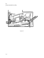
Page 129: ...unit see page 1 6 32 2 Remove the exposure lamp see page 1 6 34 3 Unhook two mirror A holders and then remove the scanner mirror A Scanner mirror A Scanner mirror A Hook Mirror A holder Scanner mirror A Hook Mirror A holder Figure 1 6 43 Removing the scanner mirror A ...

Page 130: ...the connector from the scanner PWB Figure 1 6 44 Removing the scanner motor 1 5 Remove two screws and then remove two grounding plates Figure 1 6 46 Removing the scanner motor 3 Connector Scanner PWB Screws Scanner belt Grounding plates Screw Screw Figure 1 6 45 Removing the scanner motor 2 6 Loosen two screws and then release the tension of a scanner belt 7 Remove the scanner belt ...

Page 131: ...ate Stopper ring Scanner shaft Figure 1 6 48 Removing the scanner motor 5 Figure 1 6 47 Removing the scanner motor 4 9 Remove the stopper ring and then detach the scanner shaft Detach the shaft taking care to tilt it as little as possible Grounding plate Screws Screw ...

Page 132: ...t Cable Cable clamps 10 Remove the cable from the cable clamps 11 Remove four screws and then remove the scanner motor mount with scanner motor Figure 1 6 49 Removing the scanner motor 6 12 Remove the screw and then remove the scanner motor Figure 1 6 50 Removing the scanner motor 7 ...

Page 133: ...from the machine see page 1 6 2 2 Unlatch three snaps and remove the main charger cap 3 Draw the main charger unit in the direction of arrow A then pull it out in the direction of arrow B Figure 1 6 51 Removing the main charger unit CAUTION When refitting the main charger unit hold terminal down C then push frontwards Use care not to deform the terminal ...

Page 134: ...y 70 to 70 Changing the value by 1 moves the leading edge by 0 254 mm Press the start key to output a test pattern Printing cannot be stopped until the preset number of sheets is printed Lead Edge Adj1 Leading edge registration from the drawer Lead Edge MPT Leading edge registration from the MP tray 1 6 17 Adjustment the maintenance mode 1 Adjusting the leading edge registration of image printing ...

Page 135: ...djusted using up down cursor keys After adjusting the MP tray adjust the drawer VTC Cas 1 Center line from the drawer VTC MPT Center line from the MP tray VTC Cas 2 Center line from the optional drawer Press the start key to output a test pattern Printing cannot be stopped until the preset number of sheets is printed 2 Adjusting the center line of image printing Make the following adjustment if th...

Page 136: ...the value the smaller the amount of slack The new setting is stored Select the item to be adjusted using up down cursor keys Is the leading edge missing or varying randomly copy example 1 Is the copy paper Z folded copy example 2 Press the system menu counter key Increase the value using the right cursor key Press the system menu counter key Decrease the value using the left cursor key Press the e...

Page 137: ...2 Figure 1 6 55 Enter maintenance mode Enter 065 using up down cursor keys Yes No Start End Press the system menu counter key Place an original and press the start key to make a test copy Printing cannot be stopped until the preset number of sheets is printed Is the image correct Setting range 25 to 25 Initial setting 0 Changing the value by 1 changes the magnification by 0 1 Increasing the value ...

Page 138: ... using the right cursor key For copy example 2 decrease the value using the left cursor key Press the enter key The new setting is stored Press the enter key Select Sub Scan Adj auxiliary scanning direction using up down cursor keys End Press the back key to exit maintenance mode 5 Adjusting magnification of the scanner in the auxiliary scanning direction Perform the following adjustment if the ma...

Page 139: ... down cursor keys Press the enter key Press the system menu counter key Place an original and press the start key to make a test copy Printing cannot be stopped until the preset number of sheets is printed Press the system menu counter key For copy example 1 decrease the value using the left cursor key For copy example 2 increase the value using the right cursor key Press the enter key The new set...

Page 140: ... the system menu counter key Place an original and press the start key to make a test copy Printing cannot be stopped until the preset number of sheets is printed Is the scanner center line correct Press the enter key The new setting is stored Setting range 66 66 Initial setting 7 Changing the value by 1 moves the center line by 0 1 mm Press the system menu counter key For copy example 1 increase ...

Page 141: ...n narrower Yes No Start Enter maintenance mode Enter 403 using up down cursor keys Press the enter key A Margin Scanner left margin B Margin Scanner leading edge margin C Margin Scanner right margin D Margin Scanner trailing edge margin Place an original and press the start key to make a test copy Printing cannot be stopped until the preset number of sheets is printed Press the enter key The new s...

Page 142: ...stopped until the preset number of sheets is printed Yes No Start End Press the back key to exit maintenance mode Is the image correct Enter 070 using up down cursor keys Press the system menu counter key Setting range 25 to 25 Initial setting 2 Changing the value by 1 changes the magnification by 0 1 Increase the value makes the image longer and decreasing it make the image shorter Press the syst...

Page 143: ... conter key For copy example 1 decrease the value using left cursor key For copy example 2 increase the value using the right cursor key Press the system menu conter key Press the back key to exit maintenance mode Place an original on the DP and make a test copy Printing cannot be stopped until the preset number of sheets is printed Is the image correct Setting range 32 to 32 Initial setting 11 Ch...

Page 144: ...py Printing cannot be stopped until the preset number of sheets is printed Is the image correct Setting range 42 to 32 Initial setting 0 Changing the value by 1 moves the copy image by 0 293 mm Press the enter key The new setting is stored Select Trail Edge Adj DP trailing edge registration using up down cursor keys Original Copy example 1 Copy example 2 11 Adjusting the DP trailing edge registrat...

Page 145: ...ginal on the DP and make a test copy Printing cannot be stopped until the preset number of sheets is printed Yes No Start End Press the system menu counter key For copy example 1 increase the value using the right cursor key For copy example 2 decrease the value using the left cursor key Press the back key to exit maintenance mode Is the image correct Enter 072 using up down cursor keys Press the ...

Page 146: ... margin narrower Yes No Start Enter maintenance mode Enter 404 using up down cursor keys Press the enter key A Margin DP left margin B Margin DP leading edge margin C Margin DP right margin D Margin DP trailing edge margin Place an original on the DP and press the start key to make a test copy Printing cannot be stopped until the preset number of sheets is printed Press the enter key The new setti...

Page 147: ... quit the web browser displaying COMMAND CENTER After completing the firmware upgrading restart the web browser to connect to COMMAND CENTER as necessary Procedure 1 Turn the power switch off and disconnect the power plug 2 Remove the pin and then remove the memory cover 3 Remove two screws and then remove the CF cover 4 Insert Compact Flash in a CF slot on the main PWB Insert it straight all the ...

Page 148: ... then remove the memory cover 3 Remove the DIMM from the DIMM slot on the main PWB 4 Insert the new DIMM into the DIMM slot on the main PWB Insert the DIMM securely all the way into the slot If the power switch is turned on when the DIMM is not properly inserted the main PWB may be damaged 5 Refit the memory cover 6 Insert the power plug and turn the power switch on DIMM slot DIMM Figure 1 7 3 ...

Page 149: ... up tray as manipulated by the user The figure below shows the components in the paper feeding system and the paths through which the paper travels The sensors clutches etc are described in the following pages Figure 2 1 1 Paper feeding path 6 4 4 0 8 7 9 2 1 3 5 1 Cassette 2 MP tray 3 Face down output tray 4 Face up output tray 5 Process unit 6 Fuser unit 7 Feed roller 8 Feed pulley 9 MP feed rol...

Page 150: ...sor Feed clutch MP feed clutch Registration sensor Registration clutch Engine PWB Main motor EXITN MOTORN REGDRN RESIT PAPERN MPFDRN FEDDRN HANDSN YC7 7 YC8 5 YC5 2 YC4 1 YC9 2 YC4 9 YC6 2 YC8 7 1 MP feed roller 3 Lower registration roller 4 Upper registration roller 5 Transfer roller 6 Heat roller 7 Lower exit roller 8 Upper exit roller 2 Feed roller Power train 2 3 4 5 7 8 6 1 Drum Developing ro...

Page 151: ...transfer roller Driving power train 1 Main motor gear 2 Registration clutch 3 MP feed clutch 4 Feed clutch 5 MP feed roller 6 Feed roller 7 Registration gear Z13 8 Registration gear Z20 9 Gear 53 0 Lower registration roller Upper registration roller Transfer roller TC gear Z18 Press roller Heat roller Heat gear Z33 Lower exit roller Exit gear Z23 Upper exit roller Exit gear Z23 UP Gear 21 Gear 95 ...

Page 152: ... 1 Original holder 2 Scanner upper frame 3 Scanner lower frame 4 Contact glass 5 DP Contact glass 6 Scanner rail 7 Scanner motor mount 8 Tension pulley mount 9 Scanner belt 0 Scanner motor Tension pulley Scanner gear 45 18 Scanner gear 39 22 Scanner shaft ISU housing CCD image sensor Exposure lamp Exposure lamp mount CCD PWB ISU lens Mirror A Mirror B Mirror A Scanner home position sensor 1 5 8 2 ...

Page 153: ...YC3 3 YC11 9 YC11 10 YC11 11 YC1 5 YC1 14 YC1 12 YC1 10 YC1 8 YC1 6 YC1 18 YC1 20 YC1 22 YC1 29 30 CN11 1 CN11 4 Scanner PWB Engine PWB Main PWB Inverter PWB Exposure lamp ISU unit Scanner unit CCD PWB Original Scanner motor Scanner home position sensor CN10 4 SW SWN CCDCLKN CCDCLK RSN CPN SH CCDG O CCDB E CCDR CCD image sensor LAMP LAMP LAMPHI LAMPLOW HPSWN ...

Page 154: ...nput through reflection by the three mirrors and through the ISU lens to the CCD image sensor on the CCD PWB The CCD image sensor scans one row of the image in the main scan direction converts it to electric signals and outputs them to the main PWB Then the ISU unit is moved in the sub scan direction along the scanner shaft and the CCD image sensor scans the next row of the image in the main scan ...

Page 155: ...ides technical details on the machine s electrophotography system 1 Electrophotographic cycle The electrophotography system of the machine performs a cyclic action made of six steps as follows Each step is technically explained in the following sections Figure 2 1 7 Electrophotographic cycle The sections for main charging exposure drum developing and cleaning are modularized in one Process unit 2 ...

Page 156: ...ain unit C For main unit Transfer roller D For toner container 1 Main charger unit 2 Charger wire 3 Grid 4 Developing roller 5 Gear Z14 Z18 6 Gear Z14 Z36 7 Gear Z18 Z36 8 Free gear Z40 9 Gear Z18 Z35H 0 MAG gear Z24H Mixer gear Z20 B Mixer gear Z20 A DLP screw B DLP screw A Drum Drum gear Z35H Drum shaft Drum gear Z36 Sweep gear Z13 Idle gear 18H Cleaning blade Sweep roller Waste toner reservoir ...

Page 157: ...uch as a screwdriver etc resulting in a print quality problem Also finger prints can cause deterioration of the OPC layer therefore the drum in the process unit must be handled with care Substances like water alcohol organic solvent etc should be strictly avoided As with all other OPC drums the exposure to a strong light source for a prolonged period can cause a print quality problem The limit is ...

Page 158: ...ve layer is given a uniform positive corona charge dispersed by the main charger wire Due to high voltage scorotron charging the charging wire can get contaminated by oxidization after a long run Therefore it must be cleaned periodically from time to time Cleaning the charging wire prevents print quality problems such as black streaks High voltage PWB MHVDR1 Main charging output Main charger unit ...

Page 159: ...t Figure 2 1 11 Exposure The laser beam 780 nm wavelength beam is dispersed as the polygon motor polygon mirrors revolves to reflect the laser beam over the drum Various lenses and mirror are housed in the scanner unit adjust the diameter of the laser beam and focalize it at the drum surface Drum Laser scanner unit ...

Page 160: ...rence each mirror corresponding to one scanned line width on the drum when laser beam scans on it 4 F theta lens The f theta lens equalizes focusing distortion on the far ends of the drum 5 Sensor mirror Bends the very first shot of a laser scan towards the beam detection sensor 6 6 Pin photo sensor When shone by the sensor mirror above this photo sensor generates a trigger signal for the engine c...

Page 161: ... electrical resistance of the photoconductor is reduced and the potential on the photoconductor is also lowered Resulted on the drum surface is an electrostatic image which represents the data to print Note that the area to be printed black has the low potential constituting a positively exposed image Figure 2 1 13 Drum surface potential Aluminum cylinder OPC layer Laser beam Charged surface poten...

Page 162: ...r is applied with the AC weighted positive DC power source Toner on the developing roller is given a positive charge The positively charged toner is then attracted to the areas of the drum which was exposed to the laser light The gap between the drum and the developing roller is approximately 0 3 mm The non exposed areas of the drum repel the positively charged toner as these areas maintain the po...

Page 163: ...rum and the transfer roller Figure 2 1 15 Transfer The nominal transfer bias is set to approximately 1 8 kV limit with the 6 mA current Since the ideal potential of the transfer bias depends on the thickness of paper the bias is raised to approximately 2 5 kV 6 mA for thicker paper On the other hand the bias current is reduced to 1 8 kV 6 mA for thin paper High voltage PWB HVISEL THVDR PSEL1 Trans...

Page 164: ... roller surface as doing so may result in print problems The heat roller has four claws which are continuously in contact with its surface These claws prevent the paper on which toner has been fused from being wound around the heat roller causing paper jam The pressure roller is made of the heat resistant silicon rubber This roller is used to strongly press the paper towards the heat roller by mea...

Page 165: ...Figure 2 1 17 Fuser unit mechanism 0 1 2 3 4 5 6 7 8 9 1 Heat roller 2 Idle gear Z34 3 Exit gear Z23 4 Idle gear Z18 5 Heat gear Z33 6 Press roller 7 Heater lamp 8 Thermal cutout 9 Separator s 0 Thermistor Exit pulley s Lower exit roller ...

Page 166: ...waste toner reservoir Figure 2 1 18 Drum cleaning and erasing static charge After the drum is physically cleaned it then must be cleaned to the electrically neutral state This is necessary to erase any residual positive charge ready to accept the uniform charge for the next print process The residual charge is canceled by exposing the drum to the light emitted from the eraser lamp This lowers the ...

Page 167: ...switch 5 Bias PWB E Cassette switch F Registration sensor G Paper sensor 6 Main motor 7 Cooling fan 8 Registration clutch 9 Feed clutch 0 MP feed clutch MP paper sensor Toner sensor PWB Waste toner sensor PWB Eraser lamp PWB Laser scanner unit Heater lamp Thermal cutout Thermistor Paper feeder interface connector Figure 2 2 1 Main unit 1 6 B A C 3 D 4 7 F5E 08 G 9 2 ...

Page 168: ...2GM 2 2 2 2 Scanner unit 1 Operation PWB 2 CCD PWB 3 Scanner PWB 4 Inverter PWB 5 Scanner home position sensor 6 Scanner motor 7 Exposure lamp Figure 2 2 2 Scanner unit 2 4 6 3 5 7 1 ...

Page 169: ...3 API ROM socket YS4 CODE DIMM YS1 SDRAM U14 15 SDRAM DIMM slot YS2 FAX control PWB YC1 Compact Flash socket YC2 Font ROM U12 Transceiver U4 6 8 10 RTC U11 Latch U5 7 9 Scanner I F YC6 Laser scanner unit YC8 Parallel I F YC3 USB YC4 Ethernet YC5 Front panel YC13 Engine I F YC7 Debugger I F YC10 EEPROM YS5 CCDRD CCDBED CCDGOD CCDSH CCDCLP CCDRS CCDCLK CCDSW 1 0 AUDIO FRRSTN PANTXD PANRXD PANRTS PAN...

Page 170: ...ram YC10 U30 U28 U29 YC7 YC13 YC1 U26 YC8 1 20 1 1 13 1 1 1 5 1 1 38 50 A1 B1 A30 B30 20 9 8 YC2 U14 U15 U34 X8 X10 U11 YS5 X3 X1 U35 YC9 U2 U40 X4 U27 U1 U22 X7 YC5 X6 U21 YC4 U5 U10 U8 U7 U6 U9 U4 YS1 YS2 U12 U20 U41 U39 YS4 U23 U24 YC6 YC3 U42 U13 ...

Page 171: ...und A26 D5 O Data bus D5 A27 D3 O Data bus D3 A28 D1 O Data bus D1 A29 GND Ground A30 NC Not used B1 NC Not used B2 TXDREQ I TXDREQ signal B3 3 3 V O 3 3 V DC power supply B4 A15 O Address bus A15 B5 A14 O Address bus A14 B6 A12 O Address bus A12 B7 A10 O Address bus A10 B8 A8 O Address bus A8 B9 A7 O Address bus A7 B10 A5 O Address bus A5 B11 A3 O Address bus A3 B12 A1 O Address bus A1 B13 3 3 V ...

Page 172: ... D2 24 WP Not used 25 CD2n I CD2 signal 26 CD1n I CD1 signal 27 D11 O Data bus D11 28 D12 O Data bus D12 29 D13 O Data bus D13 30 D14 O Data bus D14 31 D15 O Data bus D15 32 CE2n O CE2 signal 33 VS1n O VS1 signal 34 IORDn O IORD signal 35 IOWRn O IOWR signal 36 WEn O WE signal 37 RDY BSYn Not used 38 VCC O 3 3 V DC power supply 39 CSELn O CSEL signal 40 VS2n Not used 41 RESET O Reset signal 42 WAI...

Page 173: ...I Not used 1 VBUS I VBUS signal 2 DATA O DATA signal 3 DATA O DATA signal 4 GND Ground 1 TXOP O TXOP signal 2 3 3 V O 3 3 V DC power supply 3 TXON O TXON signal 4 RXIP I RXIP signal 5 3 3 V O 3 3 V DC power supply 6 RXIN I RXIN signal 7 NC Not used 8 GND Ground 9 3 3 V O 3 3 V DC power supply 10 LEDL I LEDL signal 11 3 3 V O 3 3 V DC power supply 12 LEDN I LEDN signal 1 SHRGB O RGB shift signal 2 ...

Page 174: ...EGSI signal 12 PDMASKN I PDMASKN signal 13 SBSY I SBSY signal 14 SDIR I SDIR signal 15 EGRN I EGRN signal 16 SGND Ground 17 RSTN I RSTN signal 18 SGND Ground 19 OVSYNC I OVSYNC signal 20 SGND Ground 1 SGND Ground 2 SAMPLEN O SAMPLEN signal 3 VDATA O VDATA signal 4 OUTPEN O OUTPEN signal 5 SGND Ground 6 5 V O 5 V DC power supply 7 SGND Ground 8 PDN I Horizontal synchronization signal 1 5 V O 5 V DC...

Page 175: ...MHVDR THVDR RTHDR HVISEL HVCLK Regist ration sensor Paper sensor MP paper sensor 5 V DC output circuit TNFULL TONER SLEEP EXITN ZCROSS HEATN THERMA FAN1 RESIT Main motor Engine PWB CPU U1 EEPROM U5 Toner sensor Cassette switch SWIN PAPERN 24V2 5V HANDSN ERASER Optional paper feeder Optional DP PFSEN PFPFPER PFCLK FAN2 Heater lamp control circuit Zero cross signal detection circuit AC input 24 V DC...

Page 176: ... 3 8 Figure 2 3 4 Engine PWB silk screen diagram YC11 YC15 2 1 2 1 3 1 10 1 13 1 10 1 3 1 1 16 1 15 3 1 3 1 1 7 5 1 2 1 20 1 5 1 YC10 YC13 YC14 YC7 YC8 YC6 YC9 YC4 YC3 YC2 YC5 YC16 YC1 U3 U6 U1 U5 U7 X1 YC12 ...

Page 177: ... applies to the eraser lamps The eraser lamps thus illuminate as the current flows through the eraser lamp the pin 2 of connector YC14 resistors R109 R110 and R111 transistor Q18 and the ground GND PGND 1 2 3 2 3 1 Q16 R109 R110 R111 ERASER 24V3 YC14 ERASPW Eraser lamp PDL15 AD15 86 CPU U1 ERASER Engine PWB Eraser lamp cotrol circuit Figure 2 3 5 Eraser lamp control circuit ...

Page 178: ...he transition of alternating plus and negative current and detects the zero crosses This detector derives the resultant ZCROSS signal at its pin 20 of the engine CPU U1 Since abrupt change in the current flow can be significantly avoided by synchronizing triac TRC1 with the zero cross signal the possibility of noise due to the primary AC supply is greatly reduced Figure 2 3 6 Heater lamp control c...

Page 179: ... as the heater lamp is energized for the 6 positive and negative envelops out of 10 The duty cycle is 0 since the heater lamp is kept turned off for the whole envelops CPU U1 selectively switches among those variations for applying voltages to the heater lamp according to the THERMA signal which appears at pin 98 as feedback A fraction of THERMA is applied to pin 2 of comparator U6 1 The comparato...

Page 180: ...On On On On On On On On On On On Off Off On On Off On On Off On On Off Off On Off Off Off Off Off Off Off Off Off Off Off Off On Off Off On On Off Off Variation No 4 Duty 40 Variation No 5 Duty 0 Heater lamp turn on pattern in 1 cycle 10 half waves AC wave 1 2 3 4 5 6 7 8 9 10 0 V 0 V 0 V 0 V 0 V Conductivity staus of Triac TRC1 Zero cross point ...

Page 181: ...e When PLL control IC IC1 finds that the polygon motor is revolving at the rated speed turns PLGDRN to L level to acknowledge the engine CPU that the rated speed has been achieved On the contrary if PLGRDYN does not turn to L level within 8 seconds since PLGDRN has been L level Figure 2 3 8 Polygon motor control circuit GND 2 2 3 3 1 1 Q16 Q17 5V 3 3V R32 PGND PGND 24V3 24V3 PGND PLGDRN PLGRDYN PL...

Page 182: ...d clutch On Off 2 PFSEN I Paper feeder control signal 3 PFPER I Paper feeder control signal 4 PFCLK O Paper feeder control signal 5 PFMDRN O Paper feeder control signal 6 PGND Ground 7 5 V O 5 V DC power supply 8 MRDYN I Main motor ready signal 9 MOTORN O Main motor On Off 10 24 V3 O 24 V DC power supply 1 24 V3 O 24 V DC power supply 2 MPFDRN O MP feed clutch On Off 1 24 V3 O 24 V DC power supply...

Page 183: ... I OSLSW On Off 8 DPCOVSWIN I DPSSW1 On Off 9 OPSWIN I DPSSW2 On Off 10 CCDSLEPN O CCD sleep signal 1 MOTA O OCM drive control signal 2 MOTNA O OCM drive control signal 3 MOTB O OCM drive control signal 4 MOTNB O OCM drive control signal 5 DPMOT0 O OFM drive control signal 6 DPMOT1 O OFM drive control signal 7 SCANMOT0 O Scanner motor drive control signal 8 SCANMOT1 O Scanner motor drive control s...

Page 184: ...2GM 2 3 16 Connector Pin No Signal I O Description YC14 Connected to the eraser lamp 1 ERASPW O 24 V DC power supply 2 ERASERN O Eraser lamp On Off 3 PGND Ground ...

Page 185: ...Over current detection circuit Power switch Current fuse Noise filter circuit Transformer T1 24 V DC rectifier smooth ing circuit 24 V DC shutoff circuit Over voltage detection circuit Photo coupler PC1 Photo Triac PC2 Triac TRC1 Heater lamp AC input 5 V DC rectifier smooth ing circuit Thermistor Cooling fan 24V1 24V1 THERM 24V2 HEATN EXITN PGND SGND 5 V FAN SLEEPN Thermal cutout Transistor Q8 ZCR...

Page 186: ...PC2 PC5 PC1 C104 C5 C101 C102 YC4 YC1 YC2 D101 D1 D102 Q1 Q20 Q502 Q522 F2 YC3 C103 Q122 Q121 T1 L1 L2 TRA1 NTC1 L N PC4 PC3 PC2 PC5 PC1 C104 C5 C101 C102 YC4 YC1 YC2 D101 D1 D102 Q1 Q20 Q502 Q522 F2 100 V 200 V Figure 2 3 10 Power supply PWB silk screen diagram ...

Page 187: ...EP 24V3 HEATN ZCROSS SLEEPN High voltage PWB Power supply PWB 5V 24V2 24V3 FET YC301 YC305 YC302 YC303 YC304 SW301 T301 VR301 U301 1 3 A1 B1 A12 B12 1 1 2 16 1 15 Figure 2 3 11 Bias PWB circuit block diagram 2 3 4 Bias PWB The bias PWB contains the developing bias output circuit registration sensor paper empty sensor and the cassette switch It also provides a liaison connection to the high voltage...

Page 188: ... Main charger Transfer roller High voltage output circuit FAN HEATN SLEEPN Control and driver circuit FET 2 3 5 High voltage PWB The high voltage PWB contains the high voltage output circuit interlock switch circuit as well as providing a liaison connection with the power supply PWB bias PWB and the engine PWB Figure 2 3 13 High voltage PWB circuit block diagram Figure 2 3 14 High voltage PWB silk...

Page 189: ...ower supply PWB is disconnected deactivating the high voltage output laser output main motor output for safety The cooling fan is an exception Since the cooling fan is directly fed with 24 V DC from the power supply unit at the primary side 24V1 of the interlock switch the cooling fan is not deactivated even the cover is open Front cover High voltage PWB Power supply unit Interlock switch Interloc...

Page 190: ...W SWN CPN and RSN based on the clock for driving the CCD sensor CCDCLK supplied from the main PWB through the scanner PWB The image signals obtained from scanning of an original are divided into three analog signals CCDR2 CCDG2 and CCDB2 for output These signals are current amplified by the amplification circuit that consists of operational amplifiers U6 and U7 and so on and transmitted to the ana...

Page 191: ...S signal 11 GND Ground 12 CCDCLK I CCD clock signal 13 GND Ground 14 CCDCLKN I CCD clock signal 15 GND Ground 16 GND Ground 17 GND Ground 18 CCDG O O Image data G green signal analog 19 GND Ground 20 CCDB E O Image data B blue signal analog 21 GND Ground 22 CCDR O Image data R red signal analog 23 12 V I 12 V DC power supply 24 5 V I 5 V DC power supply 25 5 V I 5 V DC power supply 26 HPSWN O Scan...

Page 192: ... TP191 D9 LEDG R85 K18 D1 2 1 R70 Q3 1 2 3 R67 K17 R80 K23 K41 TP206 D28 LEDG TP175 K21 TP200 TP195 D16 LEDG D8 2 1 R82 K16 K30 K36 TP171 TP157 TP166 K4 D10 LEDG TP212 R97 K44 D17 LEDG Q9 1 2 3 TP205 Q15 4 1 3 2 5 6 2 3 7 Operation PWB The operation PWB consists of key switches and LEDs The lighting of LEDs is determined by scan signals SCAN0 to SCAN7 and LED lighting selection signals LED0 to LED...

Page 193: ... V DC power supply 4 FPRST I FPRST signal 5 PANTXD I PANTXD signal 6 PANRXD O PANRXD signal 7 PANRTS I PANRTS signal 8 PANCTS O PANCTS signal 9 3 3 V I 3 3 V DC power supply 10 CHECK I CHECK signal 11 TEMP O Temperature detection data 1 SGND Ground 2 V5 O V5 signal 3 V4 O V4 signal 4 V3 O V3 signal 5 V2 O V2 signal 6 V1 O V1 signal 7 CAP2 O CAP2 signal 8 CAP2 O CAP2 signal 9 CAP1 O CAP1 signal 10 ...

Page 194: ...er home position switch MOTA MOTNA MOTB LAMP LAMPHI LAMPLOW HPSWN MOTNB ISUMOTA ISUMOTNA ISUMOTB ISUMOTNB 2 3 8 Scanner PWB The scanner PWB consists of scanner driver circuit Q1 to Q5 and exposure lamp driver circuit U1 relays signals from engine PWB main PWB operation PWB CCD PWB and optional document processor YC5 1 20 1 18 15 1 YC4 YC8 YC3 1 13 YC2 YC1 YC7 YC6 1 1 1 30 4 10 1 20 Figure 2 3 21 S...

Page 195: ...48 ms 99 ms OVSYNC HPSWN MOTA MOTNA MOTB MOTNB MOTORN MHVDR1 HVCLK FEDDRN REGDRN RESIT EXITN ERASERN RTHVDR THVDR PSEL1 HVISEL YC3 2 YC10 4 YC11 1 2 3 4 YC4 9 YC8 10 YC7 10 MHVDR2 YC7 8 YC4 1 YC6 2 YC8 7 YC7 7 YC14 2 YC8 15 YC8 13 YC7 6 YC7 2 81 ms Timing chart No 1 Continuous copying of an A4R 8 1 2 11 original onto two sheets of A4R 8 1 2 11 R copy paper ...

Page 196: ...232 ms 116 ms OVSYNC HPSWN MOTA MOTNA MOTB MOTNB MOTORN MHVDR1 HVCLK FEDDRN REGDRN RESIT EXITN ERASERN RTHVDR THVDR PSEL1 HVISEL YC3 2 YC10 4 YC11 1 2 3 4 YC4 9 YC8 10 YC7 10 MHVDR2 YC7 8 YC4 1 YC6 2 YC8 7 YC7 7 YC14 2 YC8 15 YC8 13 YC7 6 YC7 2 Timing chart No 2 Continuous copying of an A5R 5 1 2 8 1 2 original onto two sheets of A5R 5 1 2 8 1 2 copy paper ...

Page 197: ...0 ms 325 ms 275 ms 116 ms OVSYNC HPSWN MOTA MOTNA MOTB MOTNB MOTORN MHVDR1 HVCLK FEDDRN REGDRN RESIT EXITN ERASERN RTHVDR THVDR PSEL1 HVISEL YC3 2 YC10 4 YC11 1 2 3 4 YC4 9 YC8 10 YC7 10 MHVDR2 YC7 8 YC4 1 YC6 2 YC8 7 YC7 7 YC14 2 YC8 15 YC8 13 YC7 6 YC7 2 Timing chart No 3 Continuous copying of an B5R original onto two sheets of B5R copy paper ...

Page 198: ...3V ISUMOTA ISUMOTNB ISUMOTNA ISUMOTB 5V TNFULL SGND PGND 24V3 FAN2POW 1 2 YC1 YC2 YC2 YC3 YC4 YC5 YC301 YC304 YC302 YC303 YC9 YC7 YC8 YC3 YC12 YC16 1 2 3 YC13 YC5 YC6 YC4 YC10 YC11 YC7 YC8 YC6 YC13 YC14 1 2 3 1 2 3 1 2 3 ERASPW ERASERN 1 2 3 4 5 6 7 8 9 10 11 12 13 14 15 16 17 18 19 20 20 19 18 17 16 15 14 13 12 11 9 10 8 7 6 5 4 3 2 1 TEMP 5V SGND HPSWN DPDETN DPTIMSWN DPORGSWN DPCOVSWIN OPSWIN C...

Reviews: