


2GM
2-3-17
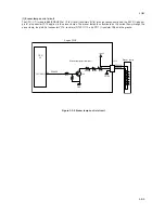
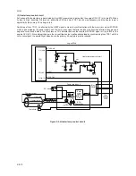
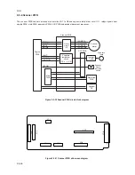
2-3-3 Power supply PWB
The power supply PWB provides the AC power input and DC power and outputs. The high voltage bias generator circuit is
mounted on a separate PWB. A simplified schematic diagram is shown below.
Figure 2-3-9 Power supply PWB circuit block diagram
FET
(Q1)
Switching/
Over
current
detection
circuit
Power
switch
Current
fuse
Noise
filter
circuit
Transformer
(T1)
24 V DC
rectifier/
smooth-
ing circuit
24 V DC
shutoff
circuit
Over voltage
detection
circuit
Photo-
coupler
(PC1)
Photo-
Triac
(PC2)
Triac
(TRC1)
Heater
lamp
AC
input
5 V DC
rectifier/
smooth-
ing circuit
Thermistor
Cooling fan
+24V1
+24V1
THERM
+24V2
HEATN
EXITN
PGND, SGND
+5 V
FAN
SLEEPN
Thermal
cutout
Transistor
(Q8)
ZCROSS
Photo-
coupler
(PC3)
(SW1) (F1)
Exit
sensor
Zero cross signal
detection circuit
Power supply unit
Summary of Contents for CD 1018
Page 1: ...Service Manual MFP Copy CD 1018 Date 17 03 2005 ...
Page 2: ...Service Manual MFP Copy DC 2018 Date 17 03 2005 ...
Page 70: ...2GM 1 5 2 2 Paper misfeed detection conditions Registration sensor Exit sensor Figure 1 5 2 ...
Page 124: ...2GM 1 6 31 Eraser lamp 9 Remove the eraser lamp Figure 1 6 35 Removing the eraser lamp ...


