39
9. Transmitter (remote
control) will not operate
the gate
1. Remove the J1 connector from the control board and then
reconnect, press transmitter button to verify operation.
2. Open the control box and press the transmitter button to
operate the gate, listen closely for a clicking sound coming
from the receiver. Click should be heard when the transmitter
button is pressed if transmitter and receiver programming
is correct and they are working correctly a sound should be
heard.
3. If click was not heard verify that “Programming transmitter
and Receiver” steps on page 22 have been completed.
4. If clicking sound was not heard, verify that transmitter battery
is good, replace if necessary.
5. If click was not heard verify that transmitter dip switches were
not changed after initial programming on page 22, if so then
reprogram transmitter to receiver following steps on page 22
or set back to original setting recorded on page 22.
6. If click was not heard verify that receiver has power applied
to it by pressing the P1 button on receiver and holding down
until green light comes “ON” then release P1. If light comes
“ON” then power to unit is correct. If light does not come
“ON” verify that connector J1 is connected to control board
correctly. If light does not come “ON” and power to receiver is
good then receiver is possibly bad.
7. If clicking sound was heard then the problem might possibly
be the control board. Verify control board is not the problem.
Perform the following steps:
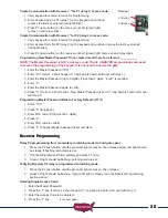
A. Remove the J1 connector from the control board
B. With J1 removed use a small screw drive to short
the center 2 pins on J1 together. When these 2 pins are
connected the gate should operate. If not the control board
has a problem perform the next step to determine the extent
of the problem.
C. Connect a short wire to the J2 connector pin 2 (J2 pin 1 is
located on the left end of J2) and then touch J2 pin 3 with the
other end of the wire gate should operate, if not control board
is bad.
D. If gate operates then remove the wire from J1 pin 2 on
the receiver connector and connect it to J2 pin 2, verify
operation.


