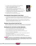
22
21
22
Making Final Adjustments
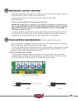
Once the gate has traveled to the stop position adjust the Gate 1 “Extend Limit More or Less”
adjustment dial located on the control board.
Turn the adjustment slightly clockwise to close gate more, cycle gate and repeat until close position is
correct. If gate is adjusted past the desired closed position turn the adjustment
counter clockwise slightly.
Then cycle the gate to verify close position is correct.
Install Safety Signs
Mount the 2 included safety signs on inside and outside of the gate
area so they are clearly visible.
Programming Transmitter and Receiver
(model 433DSR2LC):
Operating frequency 433.92 MHz.
Receiver can store up to 42 unique transmitter dipswitch code settings.
Transmitter Setup:
(It is recommended that the dipswitch code be changed from
the default factory setting)
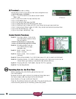
1. Open the battery compartment door and locate the dipswitches.
2. Change the dipswitches to the settings you prefer, record for future reference
in the table below.
Switch
Position
Switch
1
Switch
2
Switch
3
Switch
4
Switch
5
Switch
6
Switch
7
Switch
8
Switch
9
+
0
-
Transmitter Left Button to Receiver Programming: (standard Open/Stop/Close function)
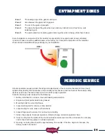
1. Press and hold the left transmitter button down. Red light on transmitter should be on.
2. On the receiver, push the P1 push-button until the green LD light comes on.
3. Release both buttons. Transmitter left button to receiver programming is complete.
Transmitter Right Button to Receiver Programming:
(Hold-Gate-Open) (Only if auto close timer is enabled)
1. The 2-channel receiver allows for programming the P2
relay from momentary mode (default) to latching mode.
Transmitter right button can be programmed to hold gate
open, over-riding the auto-close feature if activated.
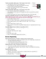
Battery
Compartment
Door
23
P1 Button
P2 Button


