


26
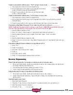
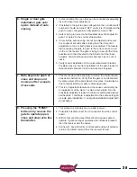
The Gate 2 kit contains linear actuator with 1 1/4” hole plug, 50 feet of 5 conductor
cable, wire nuts, junction box and mounting hardware. The Sentry control box
is equipped with two knock outs for the gate 2 linear actuator cable. One knock
out is 1 1/4” and is intended for non conduit installation (not advised). The other
knock out is 7/8” and designed for 1/2” conduit fitting for conduit installation
(recommended).
(see figure)
If conduit is being installed knock out 7/8” hole. If conduit is not being installed
knock out 1 1/4” hole.
Remove the knock out that is right for your installation.
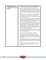
Installing Gate 2 Linear Actuator
1. Install Gate 2 linear actuator using the procedure described for the Gate 1 actuator.
The linear actuator for Gate 2 comes with an 8’ cable that must be cut and
spliced in the following manner once linear actuator is installed.
Once Actuator is installed:
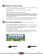
1. Locate the linear actuator cable connector and measure 18” from connector
end and cut
(see figure)
.
2. Save this 8 pin connector and pigtail for step 21 on next page.
3. Install junction box on Gate 2 hinge post below linear actuator using the 2 self
tapping metal screws.
NOTE: Sentry 300 D Gate 2 kit includes 50’ of extension cable, if
distance between control box and junction box exceeds this distance
it is recommended to purchase a cable that will not require additional
splices in the cable. Visit web page to order Sentry 300 D Gate 2
extension cable www.sentrygateopener.com.
4. If conduit is being installed attach 1/2” conduit adapter to the control box 7/8” knock out.
5. Route linear actuator cable to junction box and determine length needed (see
figure).
6. Cut cable longer than needed for future considerations (see figure).
7. Remove 2” of cable insulation to expose the 5 wires.
8. Caution: Do not damage internal wires.
9. Remove approximately 1/2” of insulation from each wire.
10. If installing conduit attach 1/2” adapter to junction box. If not, cut
rubber knock out (supplied) to fit cable.
11. Install Gate 2 extension cable into the junction box (see figure).
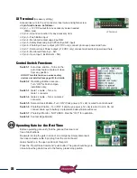
12. Using supplied wire nuts connect the 5 wires matching the wire colors (see
figure).
13. Do not install junction box cover until all connections have been completed
14. With extension cable now installed in junction box, route the other end of the
extension cable to the control box.
15. Install wires into control box wire compartment.
16. Snap 1 1/4” hole plug into control box if conduit was not used.
Control Box Knock Outs