background image

46

IF REPAIR OR REPLACEMENT IS NEEDED DURING THE WARRANTY PERIOD, THE PURCHASER 

WILL BE REQUIRED TO FURNISH A SALES RECEIPT/PROOF OF PURCHASE INDICATING 

DATE OF PURCHASE, AMOUNT PAID AND PLACE OF PURCHASE. THE PURCHASER WILL 

BE CHARGED FOR THE REPAIR OF ANY PRODUCT OR PRODUCT PART RECEIVED WITHOUT 

SUCH PROOF OF PURCHASE OR FOR REPAIRS REQUESTED OUTSIDE OF THE APPLICABLE 

WARRANTY PERIOD.

Warranty Limitations and Exclusions

This Limited Warranty ONLY COVERS failure due to defects in materials or workmanship, and 

DOES NOT COVER normal wear and tear or cosmetic damage, The Warranty ALSO DOES NOT 

COVER damages which occurred in shipment , or failures which are caused by products not supplied 

by USAutomatic, or failures which result from accidents, misuse, abuse, neglect, mishandling, 

misapplication, or alterations, faulty installation, connection to an improper  power source, set-up 

adjustments, misadjustment of controls, improper maintenance, power line surges, damage from 

acts of God such as lightning, wind, fire, flood or insects, introduction of sand, humidity or liquids, 

commercial or rental use or service by anyone other than an Authorized Sentry Repair Center.

THERE ARE NO EXPRESS WARRANTIES EXCEPT AS STATED UNDER “WARRANTY 

COVERAGE”. USAUTOMATIC IS NOT LIABLE FOR INCIDENTAL OR CONSEQUENTIAL 

DAMAGES RESULTING FROM THE USE OF THE PRODUCT, OR ARISING OUT OF ANY BREACH 

OF THIS LIMITED WARRANTY. (As examples, this excludes damages for lost time, lost calls or 

messages, cost of having someone remove or re-install Product or Product part, travel to and from 

an Authorized Sentry Repair Center, etc. The examples listed are not an exhaustive or exclusive list, 

but are illustration only). ALL EXPRESS AND IMPLIED WARRANTIES, INCLUDING ANY IMPLIED 

WARRANTIES OF MERCHANTABILITY OR FITNESS FOR A PARTICULAR PURPOSE, ARE 

LIMITED TO THE PERIOD OF THE WARRANTY.

Some States do not allow the exclusion or limitation of incidental or consequential damages, so the 

above limitation or exclusion may not apply to you. Some States do not allow limitations on how 

long an implied warranty lasts, so the above limitation may not apply to you. This warranty gives you 

specific legal rights, and you may also have other rights  which vary from State to State.

PARTS AND SERVICES WHICH ARE NOT EXPRESSLY COVERED BY THIS WARRANTY ARE  

YOUR RESPONSIBILITY.

To register your Sentry 300 online:  

www.sentrygateopener.com/Sentry_warranty.php

USAutomatic, LTD

118 Hillside Drive

Lewisville, Tx  75057

866-711-0001

Keep this information for your records

Model: ________________________ 

Serial Number*: ________________  

Date of Purchase: ____ /____ /____  

Purchased from: ________________

*Serial number can be found by opening cover and looking on the control board.

Summary of Contents for SENTRY 300 D

Page 1: ... AC Charged MADE IN THE USA www sentrygateopener com Designed to open all types of gates in all kinds of places High Quality Low Voltage Vehicular Swing Gate Opener High Quality Low Voltage Vehicular Swing Gate Opener 3 Year Warranty SENTRY 300 S 300 D ...

Page 2: ...ation 13 9 Install Sentry Control Box 14 Splicing for Sentry 300 S Linear Actuator Cable if needed 10 Sentry Plug N Go Harness 15 11 Install Battery 15 12 Install Charging System AC or Solar 16 13 Connect Charge Device to Charge Controller 17 14 Charge Controller Operation Check 17 15 Install Linear Actuator Cable 18 16 Sentry Plug N Go Harness Final Installation 18 17 Sensitivity Adjustments and ...

Page 3: ...ed as such The Sentry Gate Opener features an easy to connect Plug N Go wiring harness that eliminates the need for any complicated wiring The only wiring required consists of two wires from the harness that must be connected to the battery positive terminal red wire and battery negative terminal black wire All components have been pre installed so that installation can typically be completed in l...

Page 4: ... with a separate access opening The gate is installed in a location where enough space is supplied between adjacent structures and the gate that when opening or closing the chance of entrapment is reduced The gate does not swing into public access areas The gate is properly installed and swings freely in both directions Do not over adjust the sensitivity adjustment to compensate for an improper ga...

Page 5: ...en made to the sensitivity current sense circuit secondary entrapment devices and all other external devices installed the safety devices must be checked again Failure to adjust and retest the gate operator can increase the risk of injury or death 13 Verify that the emergency release manual release pin can be easily removed 14 KEEP GATES PROPERLY MAINTAINED Tighten all bolts and grease hinges and ...

Page 6: ... per Manual release clip Part 610535 1 per Plug N Go Harness Part 630040 1 per 1 2 Cable Gland Part 620022 1 per Entrapment Siren Part 530015 1 per Installed Safety Sign Part 601027 2 per Transmitter Part 030210 2 per Transformer Part 520008 1 per Charge Controller Part 520007 1 per Installed LCR Receiver Part 030200 1 per Installed SENTRY 300 Series part number 020320 PARTS INVENTORY Linear Actua...

Page 7: ...ng the linear actuator mounts to the gate and hinge post Bolt on brackets are provided and are acceptable but may require frequent service to keep tight They must be very securely attached i e carriage bolts with lock nuts and washers Lag type bolts are not recommended Loose or unstable linear actuator mounts will result in improper operation IMPORTANT CAUTIONS 1 Do not perform any welding with th...

Page 8: ...ed or misadjusted gate could be damaged It is the responsibility of the installer to verify proper gate installation prior to opener installation As a general rule a gate which is to be automatically operated must be stronger and smoother than one operated manually Does the gate swing smoothly without binds or excessive resistance Swing gates should swing level and plumb to prevent the opener from...

Page 9: ...nt splicing of the actuator cable How will you charge the battery Will it be AC or Solar charged How far away is the 110 VAC receptacles for the transformer Transformer is supplied with 12 feet of cable if extension is needed use Sentry Charge Cable Extension Kit part 630050 See Appendix B pg 42 for extension cable kit information and recommended wire size chart for extension distance needed If so...

Page 10: ... so that the bolts can be securely tightened Universal Actuator Bracket The universal actuator bracket can be installed in many different ways to accommodate your gate opener installation Use the images below to help understand the mounting options for this bracket and determine the installation method you are going to use The images are for reference only and your installation might differ Univer...

Page 11: ...lightly Another installation method would be to install as a Pull to Open and place linear actuator on outside of property Push to open installation can be achieved by installing universal actuator bracket and actuator bracket as shown in figure below Dimensions for this install method are 7 and 4 from hinge center Universal actuator bracket hole pattern allows for the actuator bracket to be insta...

Page 12: ...f post from the universal bracket 2 Install with carriage bolts lock nuts and washers 3 Tighten nuts securely Welding is the recommended method of securing the linear actuator mounts to the gate and hinge post Bolt on brackets are provided and are acceptable but may require frequent service to keep tight They must be very securely attached i e carriage bolts with lock nuts and washers Lag type bol...

Page 13: ...ket to universal actuator bracket 2 Verify that actuator bracket pivot hole dimension is located in the correct position see page 10 for dimensions 3 Tighten bolts securely Install Linear Actuator to Actuator Bracket The actuator can be mounted in two different positions as shown Installing the actuator on its side can allow for hiding it behind a cross member in the gate frame The gates below are...

Page 14: ...m bracket 6 Attach bracket to gate if using a light weight tubular farm gate use gate support bracket for support Use the 1 4 x 2 1 2 or 3 1 4 tap bolts depending on gate thickness four 1 4 flat washers and two 1 4 nylon lock nuts Tighten securely 7 Attach actuator to the now secured gate bracket using manual release pin and clip 8 The gate should now be fully opened with the actuator attached 9 V...

Page 15: ...to avoid problems Determine the length of additional linear actuator cable needed and either build it yourself or visit www sentrygateopener com for ordering the length of extension cable needed 1 Locate the linear actuator 8 pin connector Measure 18 from connector and mark 2 Cut cable at the 18 mark This will allow enough cable to be spliced and placed in the wire compartment 3 Bring extension ca...

Page 16: ...cal size must not exceed 9 wide 7 tall and 5 3 4 deep The Plug N Go harness has two 1 4 ring terminals to connect to bolt type battery post CAUTION Do not install wet cell battery into control box this type of battery usually has removable caps used for service and will vent corrosive fumes into control box 1 Install the battery into the battery compartment 2 Connect O ring terminals from harness ...

Page 17: ...ar Panel Kit Part Number 520015 not included The location of the solar panel is critical for proper battery charging The panel needs to face a South to Southwest direction and be installed at the angle of the supplied solar panel bracket For proper operation the panel must have unobstructed sun The Solar Panel needs to be mounted so that it receives full sunlight Even a small amount of shade or bl...

Page 18: ...n for 3 seconds then charging light comes on Solar Panel 1 Charge light flashes for 3 seconds and goes off 2 Solar power and detection lights come on 3 Detection light stays on for 3 seconds then charging light comes on If External Power or Solar Power LED is on and the Detection LED is on the battery is not connected to the charger Verify Red Black connectors are plugged into the bottom of the ch...

Page 19: ...ol box 3 Charge device cable is routed into control box and connected to the charge controller 3 Linear actuator cable is routed into control box Verify the above items have been completed correctly before continuing If necessary correct before proceeding If completed procede with the following steps 1 Locate the power connector attached to the linear actuator cable red and black wires 2 Connect i...

Page 20: ...s the primary safety control designed into the control board The adjustment dials control the amount of force the gate can apply to an object before the gate will stop and reverse direction If the gate senses an obstruction it will reverse direction If it senses a second obstruction before reaching the fully open or closed position the gate will shut down The entrapment alarm which is preinstalled...

Page 21: ...not auto close This is a designed in safety feature required by UL325 The transmitter can be used to close the gate and return opener back to normal operation Extend and Retract Limit Adjustments Gate open and close stop position Sentry control board limit adjustments are simple and easy to use Control board has 4 adjustment dials for adjusting the desired stop positions see figure below If opener...

Page 22: ...led see page 29 for details Switch 2 Operating direction reverse Turn ON for Push to Open installation only Switch 3 Gate 1 enable Turns on Gate 1 connector Switch 4 Gate 2 enable Turns on Gate 2 connector Switch 5 Solenoid Lock Enable Turn ON if lock power 12 vdc is wired to control board Switch 6 Photo Eye Enable Turn ON if photo eye power 12 vdc is wired to J2 6 Do not connect photo eye to batt...

Page 23: ...d from the default factory setting 1 Open the battery compartment door and locate the dipswitches 2 Change the dipswitches to the settings you prefer record for future reference in the table below Switch Position Switch 1 Switch 2 Switch 3 Switch 4 Switch 5 Switch 6 Switch 7 Switch 8 Switch 9 0 Transmitter Left Button to Receiver Programming standard Open Stop Close function 1 Press and hold the l...

Page 24: ...D light comes on then release Green LD light should be flashing 2 While the LD light is flashing push the P1 push button down and release Green LD light should be steady Momentary mode is set Erasing Single Transmitter from Receiver Memory The dipswitch settings of the transmitter to be deleted must be known If known follow the steps below 1 Set the dipswitches in a transmitter to match the switch...

Page 25: ...ity All accessories and secondary safety devices must be checked Secondary safety devices need to be checked at least once a month for proper operation Periodic checking is also advised for the following 1 Battery terminals for corrosion clean with baking soda solution 2 Hinges and pivot points need to be greased 3 Mounting bolts for correct tightness 4 Inspect weld points for cracks or other defe...

Page 26: ...t 620320 4 per Wire Nut Part 620310 6 per 3 8 x 2 5 Shoulder Bolt Part 610512 3 per 3 8 x 8 Carriage Bolt Part 610510 2 per 1 4 x 20 x 3 1 2 Tap Bolt Part 610522 2 per 1 4 x 20 x 2 1 2 Tap Bolt Part 610520 2 per 8 x 3 4 Self tap hex screw Part 610615 2 per 3 8 x 16 nylon lock nut Part 610518 5 per 1 4 x 20 nylon lock nut Part 610526 2 per 3 8 USS flat washer Part 610514 6 per 3 8 SAE flat washer P...

Page 27: ... tapping metal screws NOTE Sentry 300 D Gate 2 kit includes 50 of extension cable if distance between control box and junction box exceeds this distance it is recommended to purchase a cable that will not require additional splices in the cable Visit web page to order Sentry 300 D Gate 2 extension cable www sentrygateopener com 4 If conduit is being installed attach 1 2 conduit adapter to the cont...

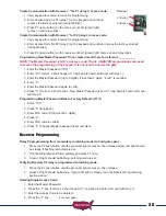
Page 28: ...nnections are made place wires in wire compartment Preparing to Operate Gate 2 for the First Time Using the Open Close Command button on the control board open Gate 1 This is done because Gate 2 was just installed in the open position and now both gates should be in the open position Operating Gate 2 for the first time and final adjustments 1 Locate the control switches and turn on switch 4 press ...

Page 29: ... pad The button is a pressure sensitive pad Press the pad an audible tone is generated Programming is identical to transmitter programming Installation hardware is included 7 Day Timer Solar friendly device Part Number 550015 The optional 7 day timer can be used to open the gate at a preset time and if the auto close feature of the gate operator is being used the gate can then close automatically ...

Page 30: ...g the same line and at the same height Remove the cover from both units Attach back plate to the installation site using mounting holes in back plate If conduit is being used recommended knockouts are provided in the unit for 1 2 conduit fitting Install wires into unit and strip 1 4 of insulation to prepare for wiring connections Connect both conduits to a weather tight junction box Then connect a...

Page 31: ...are included Low amperage rack and pinion driven Spring loaded self latching locking mechanism Wireless Keypad PUK code__________ Part Number 050520 This tamper resistant weatherproof programmable Multi code Wireless Keypad can be mounted outside your gate and offer convenient access without having to carry a transmitter Compatible with all USAutomatic wireless products long battery life 24 access...

Page 32: ...l to the receiver Valid access code was entered This is the Blue 5 key on the metal keypad NOTE Do not install keypad until Create Communication with Receiver P1 relay 1 has been completed Keypad Programming Create Access Code Code you use to operate the gate CAN NOT BE THE SAME AS THE MASTER PASSWORD 1 Enter the Master Password 11111 this is the factory default master password 2 Enter 9 If correc...

Page 33: ...n 5 digits or B is required 4 Enter 8 5 Enter the Master Password again to verify 6 Press 8 If correct 2 short beeps New Master Password is set If 1 long beep is heard start over with step 1 Programming Master Password Back to Factory Default 11111 1 Enter 11111 2 Press 8 long beep 3 Enter PUK code PUK must be 5 digits 4 Press 8 5 Enter PUK code to confirm 6 Press 8 2 beeps Master password reset c...

Page 34: ...ure Example of random positioning of the virtual dipswitches to create a Security Code is shown below To enter the Security Code enter the dipswitch number followed by the dipswitch position character The Security Code would be entered as 1 20 3 4 5 6 7 80 9 Dipswitch Position Switch 1 Switch 2 Switch 3 Switch 4 Switch 5 Switch 6 Switch 7 Switch 8 Switch 9 or B X X X 0 X X or A X X X X Use table b...

Page 35: ...justments are the primary safety feature If the gate comes in contact with an object it will stop and reverse These adjustments control the amount of force applied to an object before reversing the gate Charge Controller Located inside the control box see page 17 This is the battery charger The input power for this device can be either from the transformer supplied or the Sentry Solar Panel Part 5...

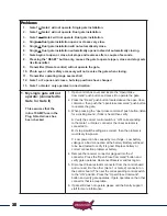
Page 36: ... Command push button and press it to operate the gate 2 Press the Reset push button located above the open close command then push the open close command push button to operate the gate 3 When pressing the open close command push button listen for a clicking sound if click is heard then verify A Verify the correct control switch is ON corresponding to the Gate 1 or Gate 2 connector the linear actu...

Page 37: ... operating then the problem is most likely the linear actuator D If voltage is not present when gate should be operating then move back to the control box side and check voltage on same two wires located in the wire compartment E If voltage is present on the control box side of drive then the cable in the ground must be damaged F If voltage is not present in the control box then we have missed som...

Page 38: ... fully open position 1 Locate the Open Close Command push button press the button to verify that the gate will close If gate closes correctly then proceed to the steps below If gate will not close go to step 5 2 Verify that control switch number 1 is turned ON Gate must be cycled once switch is turned ON for control board to recognize switch setting 3 If your installation is a single gate verify w...

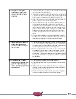
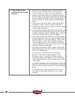
Page 39: ...tallation of the gate bracket or linear actuator bracket Verify and correct as required 7 Gate begins to open or close and stops and reverses after a couple of seconds 1 This occurs when the sensitivity circuit on the control board senses an obstruction Verify that the gate is not obstructed by some object at the point where it reverses Could also be due to hinges binding or gate contacting ground...

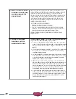
Page 40: ... not heard verify that receiver has power applied to it by pressing the P1 button on receiver and holding down until green light comes ON then release P1 If light comes ON then power to unit is correct If light does not come ON verify that connector J1 is connected to control board correctly If light does not come ON and power to receiver is good then receiver is possibly bad 7 If clicking sound w...

Page 41: ...receiver is not twisted or rolled up It should be pointing toward the control box cover 3 Some type of radio frequency interference is obstructing signal from transmitter to receiver Possible causes are electric fence high voltage electric lines in ground or overhead Radio towers in the area military bases etc In some cases this might not be avoided or possibly a different frequency receiver needs...

Page 42: ...ssories please visit www sentrygateopener com GATE CYCLES PER DAY SOLAR CHARGED SYSTEM Optional Solar Kit PN 520015 Solar charged systems should not exceed the cycles listed in the chart below These numbers are based on a single 5 watt solar panel installation If additional panels are installed additional cycles will be available Model Type REGION 1 REGION 2 REGION 3 Sentry 300 S single gate 8 cyc...

Page 43: ...ects to charge device The junction box provided should be used to keep external connections dry 3 Install DC plug connection and splice into junction box Charge Cable Extension Cable Selection Chart Transformer Extension Wire Size Chart 0 to 100 ft 101 to 250 ft 251 to 500 ft 501 to 750 ft 750 to 1000 ft 18 gauge wire 16 gauge wire 14 gauge wire 12 gauge wire 10 gauge wire Solar Extension Wire Siz...

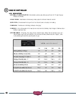
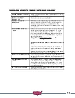
Page 44: ...city is low SYSTEM ERROR If flashing the charger has entered Failure Mode Disconnecting power will reset charger but if source of failure is not corrected Failure Mode will occur again refer to the following Table to Decode the Error Type L E D s First 4 L E D s from Left 1st 2nd 3rd 4th Wrong Battery Voltage Off Off Off Flash Reverse Battery Connection Off Off Flash Off Thermal Runaway Condition ...

Page 45: ...lowing formula to determine if the Timer may run out due to a large battery Charge Time Battery Capacity AH x 1 25 2 Calculated Charge Time must be less than approximately 108hrs Output Amps and Battery Capacity AH Ampere hour are listed on your battery or contact your battery purchasing source Example Charge time to for a fully discharged 36 AH battery 36AH 2 Amps x 1 25 22 5 Hrs ok to use EXCESS...

Page 46: ...USAutomatic during the applicable Warranty period The Warranty excludes both parts and labor for batteries and cosmetic parts such as product housing and paint finishes The Warranty only applies to Products purchased in the United States and is extended only to the original purchaser of a new product that was not sold as is Warranty Service For assistance in the continental U S A in obtaining the ...

Page 47: ...BLE FOR INCIDENTAL OR CONSEQUENTIAL DAMAGES RESULTING FROM THE USE OF THE PRODUCT OR ARISING OUT OF ANY BREACH OF THIS LIMITED WARRANTY As examples this excludes damages for lost time lost calls or messages cost of having someone remove or re install Product or Product part travel to and from an Authorized Sentry Repair Center etc The examples listed are not an exhaustive or exclusive list but are...

Page 48: ... USAutomatic LTD 2015 rev B All rights reserved No part of this may be reproduced by any means without the expressed written consent of the publisher ...

Reviews: