


43
1. My single gate will
not operate:
(Patriot I)
Verify monitored
entrapment device
switches are set
correctly see page 24
step 15.
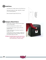
1. Remove control box cover locate the “Open/Close Command” push
button and press it to operate the gate.
2. Press the “Reset” push button located above the “Open/Close
Command” button, then push the “Open/Close command” push
button to operate the gate.
3. When pressing the “Open/Close Command” push button, listen for a
clicking sound, if click is heard then verify:
Wire harness is connected to the gear motor cable in the battery
compartment.
The 15-amp fuse located on the control board is good if not replace
it using the spare located on the control board. Also check the
dipswitches (3 and 4) for correct switch settings based on where the
actuator is connected to the control board (Gate 1 or Gate 2).
If switches are correct, fuse is good, and harness is connected and
clicking sound is heard, then the battery needs to be load tested to
determine its condition. Charge or replace the battery depending on
results.
4. Press and hold the “LED Indicator” push button and observe all of
the red LED’s
If the two limit LED’s located below the actuator plug connector
are both on the operator will not operate. You must adjust the limit
switch.
2. My gate will not
operate. Monitored
entrapment devices
are installed.
Identify the monitored
entrapment device/
devices installed - Photo
Eye or Contact Edge.
Contact Edge with 10K resistor monitoring -
1. Verify that dip switch DS2 switch 4 (contact edge monitor) is ON
pressed down on the right hand side..
2. Press and hold the LED indicator on the control board.
3. Verify the D5 LED (Contact edge 2nd entrapment) located bottom
left corner of the control board is ON dimly.
4. If not using a DC voltmeter measure the voltage on J2 pin 6 to
ground reading should be approx. 2.5 Vdc.
5. Activate the contact edge by depressing it and verify the D5 LED is
ON bright now or the voltage drops to 0 Vdc.
6. If reading is 5 Vdc then check wire connections from contact edge
for proper connection. See page 19.
7. If wire connections are correct then disconnect the contact edge
wires from the J2 connector.
8. Using an ohm meter verify the resistance measured between the 2
contact edge wires, should be 10K.
9. If not contact edge is bad.


