


19
12
13
Monitored Contact Edge (Type B2) Installation
for Entrapment Protection ONLY.
Connect wires per the table below: All wiring should be done with power disconnected from control board.
Contact Edge wiring for Entrapment Device Protection
Contact Edge Connections
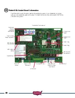
Patriot Control Board Connections
N/O connection
J2 pin 6
Common
J2 pin 2 or pin 7
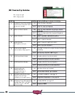
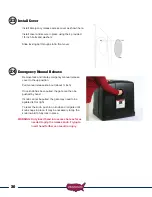
Connect Wire Harness Cable to Control Board
Before connecting the wire harness cable to the control board
check the following:
- Verify that all previous steps were performed.
- Verify that the battery connections are correct red lead to
positive and black lead to negative.
- Verify that nothing is in the path of the gate. If by chance
it begins to move when power is applied, be prepared to
disconnect the actuator cable.
The 8 pin plug on the wire harness cable must connect to either
the Gate 1 or Gate 2 connector on the control board. Once cable
is connected verify that the corresponding control switch for Gate
1 or Gate 2 is turned ON.
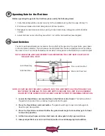
Verifying Photo Eye Installation
With power now applied to the system, the photo eye can now be installed and tested for proper
alignment. Refer to the photo eye installation instructions for information about alignment. Typically
the photo eye will have lights of different colors to indicate beam is aligned or not aligned.
11b


