background image

41

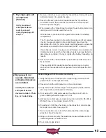
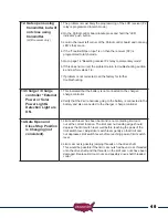
Terms and Definitions


LED

 - Light Emitting Diode - small red lights on control board.

Control board

 - Refers to Patriot control board.

Receiver

 - Located on top shelf of the operator.

Remote/Transmitter

 - Hand held unit with 2 buttons, used to operate the gate, sends signal to receiver  


when button is pressed.

Connector

 - Refers to inputs and outputs on control board where wires may be connected. 

Push Buttons

 - Three are located on the control board. “Open / Close Command” used to operate the  


 gate, “LED Indicator” used to activate the LED’s and  “Reset” used to reset the control board 

after current sensing twice before a limit is reached.

Dip Switches 

- Small switches, which are located on the control board in two places. The primary set 


 DS1,  is located in the upper left corner and the monitored set, DS2, is located in the lower 

right corner of the control board with functions listed beside each. See manual (page 22-23) 

for more information. 

Sensitivity adjustments

 - Located on the control board (see page 26). These adjustments are  


 the primary safety feature. If the gate comes in contact with an object it will stop and reverse. 

These adjustments control the amount of pressure applied to an object before reversing the 

gate.

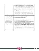
Charge Controller 

- Located inside the control box in upper left corner (see page 16). This is the battery  


 charger. The input power for this device can be either from a transformer or from a solar 

panel.

Transformer

 - This device connects to a 110 VAC electrical outlet and converts it to a low AC voltage  


that can be connected to the charge controller to provide continuous charging of the battery.

Entrapment Siren 

- If the control board sensitivity circuit senses an obstruction it will reverse the gate  


 and if a second obstruction is detected before the gate reaches a fully open or close limit the 

control board will shut down the operator and sound the entrapment alarm for five minutes or 

until the “Reset” button is pressed.

Limit Plate Assembly

 - Located on top of the operator; holds the two limit switches and also holds the    


limit cam nuts in their adjusted position.

Limit Cam Nut

 - Two limit cam nuts are located on the top of the operator; the limit plate assembly is  


 spring-loaded and must be depressed before adjusting the limit cam nut. After limit cam nut 

has been adjusted, make certain that the limit plate assembly fully engages the limit cam nut 

to keep it from rotating.

Gate Chain

 - This is the long chain connected to the gate and travels through the operator.

Drive Chain

 - This is the short chain that connects the gear motor to the manual release shaft.

Summary of Contents for PATRIOT RSL

Page 1: ...Heavy Duty Battery Powered Solar or AC Charged PATRIOT RSL Vehicular Slide Gate Operator Installation Owners Manual ...

Page 2: ...everse directions upon contacting a rigid object or when the monitored entrapment device is activated 12 After all adjustments have been made to the sensitivity current sense circuit monitored entrapment devices and all other external devices installed the monitored entrapment devices must be checked again Failure to adjust and retest the gate operator can increase the risk of injury or death 13 V...

Page 3: ...a smaller amp hour battery may cause damage to the charging system The wiring harness has two 1 4 ring terminals to connect to battery posts This type battery is commonly known as a lawn tractor or wheel chair battery If the installation is located in an area that has frequent power outages AC charged systems or might experience weeks of no sun shine solar charged systems in region 3 then a larger...

Page 4: ...tured before Jan 12 2016 that is not being upgraded to meet the current UL325 standard the Pre 2016 jumper must be installed into J5 terminal block for proper operation USAutomatic recommends upgrading all systems to current UL325 standards UL325 identifies four different classes of gate operators These classes are RESIDENTIAL VEHICULAR GATE OPERATOR CLASS I A vehicular gate operator or system int...

Page 5: ...est the roadway such as a gate support post and the gate frame when the gate is in either the fully open position or the fully closed position shall not exceed 2 1 4 in 57 mm Exception All other fixed stationary objects greater than 16 in 406 mm from the gate frame shall not be required to comply with this section Zone 3 The path the gate travels Recommended monitored entrapment protection type B2 ...

Page 6: ...B2 Installation 19 12 Connect Wire Harness Cable to Control Board 19 13 Verifying Photo Eye Installation 19 14 Patriot Control Board Information 20 15 Control Board Dipswitch Setting Verification 24 16 Optional Soft Stop for Retract or Extend Position 24 17 Operating Gate For The First Time 25 18 Limit Switches 25 19 Sensitivity Adjustment and Entrapment Alarm 26 20 Verifying Inherent Entrapment P...

Page 7: ...of children Safety Signs are installed one on each side of the gate and visible in the gate area All hard wired sensors used for monitored entrapment protection devices and their wiring are installed in a manner which protects them from mechanical damage All wireless sensors used for monitored entrapment protection devices are located so that the signal from the transmitter to the receiver is not ...

Page 8: ...purchased with LCR Radio Controls include 2 Button Transmitter Part 030210 2 per LCR Radio Receiver and Wire Harness Part 030205 1 per Antenna Part 030208 1 per Safety Signs Part 601025 2 per Optional Accessories LCR Items See accessories section pages 32 39 for complete list and descriptions 4 Button Transmitter Part 030212 Push to Operate Button Part 030215 Wireless Keypad Plastic Part 050500 Wi...

Page 9: ... Link Part 640020 4 per 1 4 x 1 Bolt Part 620012 4 per 1 4 SAE Washer Part 620013 4 per Screwdriver 1 per HARDWARE INVENTORY SAE Standard wrenches 7 16 3 4 Tape measure Clamps Chain Cutter Level Tape Measure Inch Nut Driver Phillips Head Screwdriver Needle Nose Pliers Your particular installation may require a welder drill or other hardware not included GENERAL TOOL REQUIREMENTS ...

Page 10: ...tion As a general rule a gate which is to be automatically operated must be stronger and smoother than one operated manually Does the gate slide smoothly without binds or excessive resistance Slide gates should slide level and plumb to prevent the operator from having to pull the gate up or down grade when opening or closing Is the gate frame of substantial strength without excessive weight Will t...

Page 11: ...d fully open and fully closed positions These stops shall be installed at either the top of the gate or at the bottom of the gate where such stops shall horizontally or vertically project no more than is required to perform their intended function All gates shall be designed with sufficient lateral stability to assure that the gate will enter a receiver guide ...

Page 12: ...590060 RSL Limit Switch PN 590050 Pillow Block Bearings PN 580040 1 Sprocket 21 Teeth PN 580020 Emergency Release Knob PN 680010 RSL Drive Shaft PN 610201 Safety Disk Gear Motor PN 510201 RSL Limit Nut Kit Threaded Sleeve 2 Limit Nuts PN 590057 Patriot Control Board Cover Bolt Holes 4 Plcs Post Mount Sleeve 1 13 Teeth Output Drive Sprocket PN 580010 Battery Compartment Idler Rollers Assy PN 580060...

Page 13: ...See page 17 Step 9a 5 For Solar Charged System See page 17 Step 9b 6 How will accessory control wiring if any be brought to the control box Knockouts are provided in operator base plate for conduit connections See page 14 7 Have all entrapment areas been identified See page 3 Do not mount in areas by automatic sprinklers or flood prone areas It is important that the control board control devices a...

Page 14: ...ur inch post Keep the operator parallel with the gate and level while securing in place Set the operator in place pad or post Ensure that the chain bolts once installed will be properly aligned with the chain rollers Once alignment is verified secure operator in place using bolts for pad installation and welding for post installation Keep the operator parallel with the gate while securing in place...

Page 15: ...use the dimensions that follow to install Also consider that additional bracing might be needed POST LOCATION TO GATE EDGE AND HOLE PREPARATION See illustration for operator base overall dimensions Post must be parallel to gate edge Hole depth should be at least 36 inches and bell shaped to reduce operator movement to a minimum The post must be concreted in place NOTE Remember to mount the operato...

Page 16: ... LOCATION TO GATE CONCRETE PAD ANCHOR BOLT LOCATION Concrete pad top view measures 20 x 28 This allows for 4 of concrete between the anchor bolts and the outer edge of the pad Use the drawing here to locate the four anchor bolts 2b 4 inch minimum 24 inch minimum 24 inch minimum 28 inch minimum 28 inch minimum These holes are for inch electrical conduit Use dimensions shown 28 inch minimum TOP VIEW...

Page 17: ...to be cut to the desired length To determine the desired chain length loosen the chain adjustment bolts to allow for maximum adjustment Pull the emergency release knob to allow the chain to roll freely through the operator Pull the chain to mate up with the remaining chain adjustment bolt and mark link that needs to be cut Once link is cut install master link and connect to chain adjustment bolt A...

Page 18: ...provided install Charge Controller Use a nut driver to secure c Install the receiver on top shelf using the 2 phillips screws provided d Plug the green terminal plug into the control board at J2 connector e Install entrapment siren connect wires to J4 connector on control board Black COMMON GND Red OUTPUT 12V Install Battery The charge controller harness and the operator wiring harness both must b...

Page 19: ...0 feet away from the gate area if required see Page 52 IMPORTANT Solar panel must be installed facing South Southwest direction Full sun is required any shading of the solar panel MUST be eliminated Failure to do so will result in battery charging problems Once solar panel is installed connect low voltage power plug into the charger Power In input Charge Controller Operation Check Once the power s...

Page 20: ...NECTED AND OPERATIONAL When the installation requires more than 1 monitored contact edge or 1 monitored photo eye the Monitored Entrapment Device Expansion Module must be installed USAutomatic Part 500015 Monitored Photo Eye Type B1 Installation for Entrapment Protection ONLY Connect wires per the table below All wiring should be done with power disconnected from control board Photo Eye wiring for...

Page 21: ...ons are correct red lead to positive and black lead to negative Verify that nothing is in the path of the gate If by chance it begins to move when power is applied be prepared to disconnect the actuator cable The 8 pin plug on the wire harness cable must connect to either the Gate 1 or Gate 2 connector on the control board Once cable is connected verify that the corresponding control switch for Ga...

Page 22: ...al Entrapment Siren Solenoid Lock Electric or Mag Lock Output Security Shunt DS2 Function Dip Switches Gate 2 Plug Gate 1 Plug 15 Amp Fuse Gate 1 15 Amp Fuse Gate 2 Patriot RSL Control Board Information The Patriot RSL control board is capable of operating two gates If your installation is a single gate you can operate the gate on the Gate 1 or Gate 2 connector Set control switch ON for the connec...

Page 23: ...nection monitored entrapment DS1 switch 8 must be on when monitored eye is connected Not used in pre 2016 configuration 9 Free Exit Open Input normally open contacts Loop input or any hold open input such as a 7 day timer telephone access unit or maintain contact switch normally open contacts These devices open the gate and will prevent the gate from closing if the contact is maintained Once the c...

Page 24: ...n see accessory wiring page 47 ON DS2 SW 1 must be on output 12vdc when gate is operating OFF No function See DS 2 SW 1 Pg 23 6 Soft Stop Retract Enable ON Enables soft stop for retract position OFF Disables soft stop for retract position 7 Soft Stop Extend Enable ON Enables soft stop for extend position OFF Disables soft stop for extend position 8 Photo Eye Monitor Must be ON when a monitored pho...

Page 25: ...on indicator gate leaf delay is inactive 2 Magnetic Lock Enable ON Magnetic lock output energizes on Close Limit and releases half second before gate begins to open Energizes 12 vdc output 1 5 amp max OFF Magnetic lock output is inactive 3 Security Shunt Circuit Enable Open Gate Indicator ON Security shunt circuit relay is active closed circuit wire in parallel Relay activates half second before g...

Page 26: ...h 8 and 10 ON DS2 switch 4 ON Optional Soft Stop for Open or Close Position The Patriot RSL control board is equipped with a selectable soft stop feature for open close or both directions if desired Understanding how this feature operates is required before turning ON any control switches or possible control board or gate damage may occur This feature reduces the gate speed when turned ON for appr...

Page 27: ...ction you want to adjust NOTE WHEN THE LIMIT ADJUSTMENT CAM DEPRESSES THE LIMIT SWITCH ACTUATOR THE GATE WILL STOP NOTE DO NOT ADJUST THE LIMIT CAM NUTS PAST THE LIMIT SWITCH ACTUATOR ARM THIS MAY RESULT IN DAMAGE TO THE LIMIT SWITCH ENSURE THE LIMIT PLATE ASSEMBLY SNAPS INTO THE GROOVES ON THE LIMIT CAM NUTS PRIOR TO RESUMING OPERATION 1 Locate the Open Close command button on the Patriot control...

Page 28: ...5 minutes or until the reset button on the control board is pressed and released The hard shutdown will require the reset button to be pressed to place the gate operator back into operation Verifying Inherent Entrapment Protection System Type A Operation Once the gate operator is installed use the table below to determine correct operation It is recommended that the current sensitivity adjustment ...

Page 29: ...n when the sensor is no longer actuated Return to normal operation when the sensor is no longer actuated Verifying Monitored Contact Edge Type B2 Entrapment device Operation Only Operate the gate and verify entrapment protection devices are working properly Use the table below to determine correct operation Contact Edge Type B2 Monitored Entrapment N O input J2 pin 6 If DS2 switch 4 is OFF then ga...

Page 30: ...nsmitter right button can be programmed to hold gate open over riding the auto close feature if activated 2 Press and hold the right transmitter button down Red light on transmitter should be on 3 Press the P2 push button until the green LD light comes on 4 Release both buttons Transmitter right button to receiver programming is complete Receiver Programming Relay P2 programming from momentary to ...

Page 31: ... push button until the green LD light comes on Then release both 6 Transmitter is now erased from receiver memory Erasing all Transmitters from Receiver Memory 1 Press the P2 button on the receiver until the green LD light comes on Then release P2 button 2 While LD light is on press the P1 and P2 buttons simultaneously and hold until the green LD light begins to blink slowly It should blink 4 time...

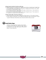
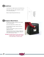
Page 32: ...er to the up position Pull manual release knob out about inch Once knob has been pulled the gate can then be pushed by hand If knob cannot be pulled the gate may need to be agitated left or right To reset the knob push in on knob and roll gate until knob snaps in place It may be necessary to tap the knob inward to fully lock in place WARNING Only insert hand into access hole as far as needed to gr...

Page 33: ...essary 3 Mounting bolts and sprocket set screws for correct tightness 4 Inspect weld points for cracks or other defects 5 Inspect wiring for cuts nicks or other defects 6 Inspect drive chain and sprockets for tension and wear Adjust or replace as necessary 7 As needed use motorcycle or bicycle chain lube to keep chain properly maintained 8 Verify proper operation of charging system refer to charge...

Page 34: ...tches like the transmitter instead it has virtual dip switches which must be programmed PUK Code Password Unblocking Key The PUK code is located inside the keypad and is needed when the master password has been lost Record in space above for future reference Must be 5 digits long Key located on the keypad is used to cancel last command entered Red Light Blinks When blinking the keypad is sending a...

Page 35: ...ual dipswitch contains nine 3 position switches To ensure neighboring keypads do not interfere with each other the virtual switches should be positioned in a random pattern using the following procedure Example of random positioning of the virtual dipswitches to create a Security Code is shown below To enter the Security Code enter the dipswitch number followed by the dipswitch position character ...

Page 36: ...r Programming Relay P2 programming from momentary to latching mode to hold gate open 1 Press the P2 push button until the green LD light comes on then release Green LD light should be steady If flashing latch mode is set 2 If not flashing release P2 immediately and press P1 once 3 Green LD light should be flashing Latching mode is set Verifying Receiver P2 relay is programmed to latching mode 1 Pr...

Page 37: ...ct the negative 12vdc wire from the magnetic gate lock to J1 Common Gnd terminal Connect the positive 12vdc wire from the magnetic gate lock to J1 Solenoid Lock terminal Exit Sensor Solar friendly device Preferred Technologies CP 3 3W Part Number 070305 The driveway exit sensor is a magnetic device that installs below ground beside the drive A magnetic field is established which when interrupted b...

Page 38: ...e control box It requires 4 wires to be installed from the unit to the control box Wire not included The second unit Transmitter should be installed on the opposite side of the drive It requires 2 wires to be installed from the unit to the control box 12v and Gnd The two units must face each other to establish the beam maximum distance 40 feet Photo Eye 550011 Battery Powered Transmitter or Hard w...

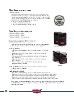
Page 39: ...1 4 Wire the RX relay common from the photo eye to J2 pin 2 or 7 5 Turn OFF DS1 switch 3 and 4 temporarily to provide power for installation 6 Turn on dipswitch DS1 switch 10 photo eye power enable 7 Install Photo eye and adjust beam verify proper operation 8 Once installed turn ON DS1 appropriate dipswitches for gate 1 or gate 2 or both for dual gates Test photo eye for proper operation when gate...

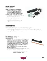
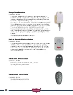
Page 40: ... in slot to open Press the learn button Then press the transmitter button that will be used to open the garage See garage operator for connecting the 2 wires supplied If needed 4 button transmitters are available Push to Operate Wireless Button Part Number 030215 The Push to Operate transmitter is designed for indoor or outdoor wireless installation Install to allow operation of the gate or garage...

Page 41: ...ion not waterproof Charge Cable Extension Pigtails Part Number 630038 Provides easy splicing of charging device cable Works with AC Transformer and Solar Panel Monitored Entrapment Device Expansion Module Part Number 500015 The expansion module is designed to monitor for the connection and proper operation of multiple monitored external entrapment devices If the installation requires more than 1 m...

Page 42: ...at are activated will be obvious by the illumination of the adjacent LED 2 The second feature to assist in troubleshooting is the current sense beeper The beeper will sound anytime the current sense circuit is activated This is useful in detecting a false reverse due to an improper or too sensitive current reverse setting or a gate which is requiring excessive force to move 3 The third feature to ...

Page 43: ...re reversing the gate Charge Controller Located inside the control box in upper left corner see page 16 This is the battery charger The input power for this device can be either from a transformer or from a solar panel Transformer This device connects to a 110 VAC electrical outlet and converts it to a low AC voltage that can be connected to the charge controller to provide continuous charging of ...

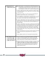
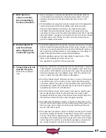
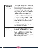
Page 44: ... closes correctly then immediately reverses direction 9 Control board 15 amp fuse blows when Open Close Command is given 10 Transmitter Remote control will not operate the gate 11 Photo eye being used for vehicular protection will not reverse the gate when closing or hold the gate open 12 Pressing the RESET button only causes the gate to operate 13 Gate opens with the transmitter but will not clos...

Page 45: ...4 Press and hold the LED Indicator push button and observe all of the red LED s If the two limit LED s located below the actuator plug connector are both on the operator will not operate You must adjust the limit switch 2 My gate will not operate Monitored entrapment devices are installed Identify the monitored entrapment device devices installed Photo Eye or Contact Edge Contact Edge with 10K res...

Page 46: ...en check wire connection from photo eye for proper connection See page 18 8 If D11 is ON verify that the D11 Led goes OFF when photo eye beam is broken 9 If D11 does not turn OFF when beam is broken then photo eye is bad 3 Emergency release knob cannot be pulled 1 If the emergency release knob cannot be pulled first verify that it is not already pulled by trying to roll the gate If gate will not m...

Page 47: ...troller Using a DC voltmeter measure the DC voltage should measure about 22 volts and the DC current should read about 300 ma in the peak sun period If either of these readings is incorrect the panel maybe defective please call the factory If none of the above check bad then remove battery and have it load tested at a battery shop Replace if bad AC charged If accessories are connected keypads loop...

Page 48: ...and hold While pushing the button inspect the LED indicators located on the control board lower left corner and note which LED s are on If any LED s are on disconnect the green J2 connector from the control board Press the Open Close Command push button to close the gate Press the button again to open the gate fully and verify the automatic close is working 6 If gate automatically closes correctly...

Page 49: ...er will not operate the gate LCR radio equipment only 1 Open the control box and locate the Patriot control board Locate the LED Indicator push button and the Push Button Input LED Push and hold the LED indicator push button then press the transmitter button and observe the Push Button Input LED The LED should come on while the transmitter button is depressed 2 If the Push Button Input LED did not...

Page 50: ...ard 3 Press and hold the LED indicator push button and observe the Safety Loop Reversing Edge Input LED Activate the accessory in question if photo eye break the beam If the accessory is working properly the LED light should come on when the device is activated If the device does not turn on the LED light check the wiring on the J2 connector and check J2 connector connection to the Patriot control...

Page 51: ...r Power Light Detection Light are ON 1 This indicated that the battery is not connected to the charger charge controller 2 Verify that the 2 wire harness going to the battery is connected to the battery and also connected to the charger charge controller 14 Gate Open and Close Stop Position is Changing not consistent 1 Limit switch lever has been bent and is not contacting limit cam nut at the cor...

Page 52: ...NLY A If your system is equipped with the USAutomatic charger charge controller part 520006 and is AC charged not solar verify the charger charge controller is properly working The external Power light should be ON and either the Charging or Charged light should be ON B If the external power light is not ON then check the 120 VAC outlet the transformer is plugged into for the correct voltage and c...

Page 53: ... correctly NOTE The one test that will verify that the charger and Power source is working properly is a DC current reading between the charger and battery 1 Disconnect the black lead from the battery 2 Set multi meter up to read DC current 3 Connect red meter lead to the black wire from the charger 4 Connect black meter lead to the neg battery post 5 If charger shows External power or Solar power...

Page 54: ...charged systems should not exceed the cycles listed in the chart below These numbers are based on a single 6 watt solar panel installation If additional panels are installed additional cycles will be available Patriot RSL REGION 1 REGION 2 REGION 3 10 Feet Travel Distance 22 cycles per day 35 cycles per day 60 cycles per day 20 Feet Travel Distance 10 cycles per day 17 cycles per day 30 cycles per...

Page 55: ...t modify the transformer or solar panel cable this will void the product warranty Charge Cable Extension Cable Selection Chart Transformer Extension Wire Size Chart 0 to 100 ft 101 to 250 ft 251 to 500 ft 501 to 750 ft 750 to 1000 ft 18 gauge wire 16 gauge wire 14 gauge wire 12 gauge wire 10 gauge wire Solar Extension Wire Size Chart 15 to 100 feet 100 to 250 feet 250 to 500 feet 18 gauge wire 16 ...

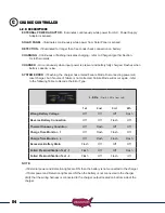
Page 56: ...ource of failure is not corrected Failure Mode will occur again refer to the following Table to Decode the Error Type L E D s First 4 L E D s from Left 1st 2nd 3rd 4th Wrong Battery Voltage Off Off Off Flash Reverse Battery Connection Off Off Flash Off Thermal Runaway Condition Off Flash Off Off Charge Time Monitor 1 Off Flash Flash Off Charge Time Monitor 2 Off Flash Flash Flash Excessive Battery...

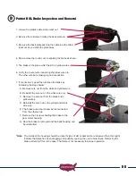
Page 57: ...e steps below A Remove wire nut from the white and yellow wire B Reinstall the wire nut on the white wire only C Remove the wire nut from the black and 2 yellow wires D Reinstall the wire nut on the yellow and black wire only E The brake wires should now be disconnected from the other wires F Remove the 3 screws holding the brake to the gear motor housing G Now the brake is removed and the back ho...

Page 58: ...ards When installing in a pre 2016 system that is not being upgraded to the current UL325 standard the pre 2016 jumper must be installed The secondary entrapment input J2 pin 6 required for pre 2016 systems is labeled on the control board as contact edge 2nd entrapment N O The J2 pin 6 input has not changed and re wiring of existing secondary entrapment devices is not required For this input to op...

Page 59: ...ssued To have the product s sent for warranty service a Return Authorization number RA will be issued which must be written on the outside of the package Packages without RA may not be accepted Packages for warranty service may be sent to the address below All repairs or replacements are at the discretion of the Manufacturer This warranty excludes items that have been abused altered incorrectly in...

Page 60: ... 800 878 7829 USAutomaticGateOpeners com ...

Reviews: