


INSTALLATION AND WIRING 2-1
2.0 INSTALLATION AND WIRING
Section 2.0 provides the information needed to
properly mount and wire the PHOENIX Drive. Since
most start-up difficulties are the result of incorrect
wiring, it is essential that the wiring is done as
instructed. Read and understand this section in its
entirety before actual installation begins.
2.1 SAFETY WARNINGS
WARNING
Only qualified electrical personnel familiar with the
construction and operation of this equipment and the
hazards involved should install, adjust, operate or
service this equipment.
WARNING
The control and its associated motors and operator
control devices must be installed and grounded in
accordance with all national and local codes (NEC,
VDE 0160, BSI, etc.). To reduce the potential for
electric shock, disconnect all power sources before
initiating any maintenance or repairs. Keep fingers
and foreign objects away from ventilation and other
openings. Keep air passages clear. Potentially lethal
voltages exist within the drive enclosure and
connections. Use extreme caution during installation
and start-up.
WARNING
The following information is only a guide for proper
installation. US Drives cannot assume responsibility
for the compliance or noncompliance to any code,
national, local or otherwise for the proper installation
of this drive or associated equipment. A hazard of
personal injury and/or equipment damage exists if
codes are ignored during the installation.
2.2 INITIAL CHECKS
Before installing the PHOENIX Drive, check the unit for
physical damage sustained during shipment. If
damaged, file a claim with the shipper and return for
repair following the procedures outlined on the back
cover. If no damage is observed, remove all shipping
restraints and padding. Check drive nameplate data
for conformance with the AC power source and motor.
2.3 DETERMINING CONTROL LOCATION
The PHOENIX Drive is suitable for most well-ventilated
factory areas where industrial equipment is installed.
Locations subject to steam vapors or excessive
moisture, oil vapors, flammable or combustible vapors,
chemical fumes, corrosive gases or liquids, or excessive
dirt, dust or lint should be avoided unless an
appropriate enclosure has been supplied or a source of
clean air is supplied to the enclosure. The location
should be dry and the ambient temperature should not
exceed 122
°
F (50
°
C). If the mounting location is
subject to vibration, the unit should be shock mounted.
2.4 MOUNTING
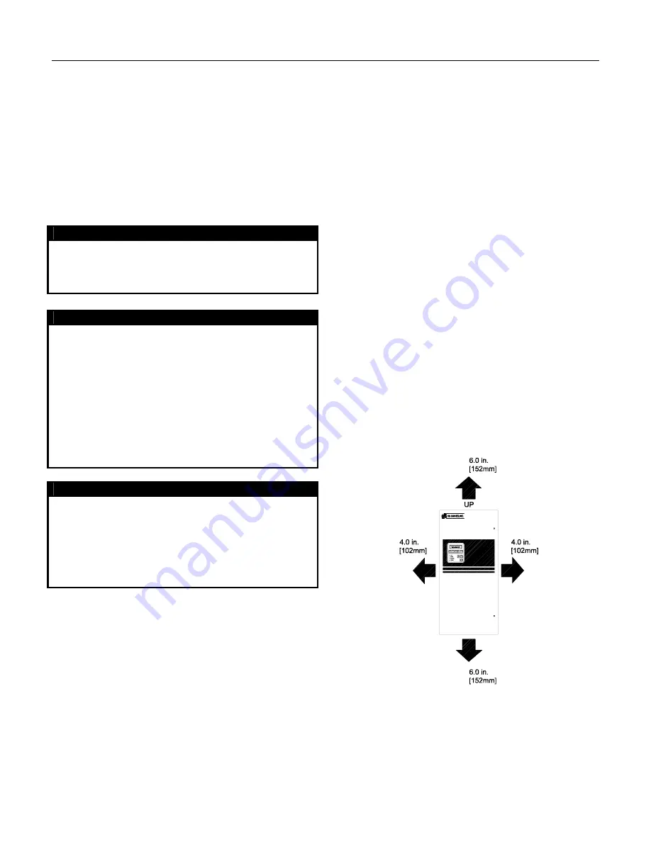
Figure 2-1 shows the minimum required surrounding
air space for panel mounted PHOENIX Drives (size 0
through size 3 units). Note that the panel mounted
units must be mounted in an upright position. Figure
2-2a shows dimensional information for size 1 through
size 2 units. Figure 2-2 shows dimensional information
for size 0. Figure 2-2b shows dimensional information
for size 3. If through panel mounting is chosen
(available on size 0 through size 3 Drives), a suitable
sealant should be applied to the mounting faces of the
drive and the panel to prevent leakage.
Figure 2-1
Minimum Required Surrounding Air
Space for size 0 through size 3
PHOENIX Drives
Summary of Contents for PHOENIX EX
Page 1: ...INSTRUCTION MANUAL PHOENIX EX 3 TO 3500 HP VECTOR AC DRIVE ...
Page 12: ...1 8 INTRODUCTION END INTRODUCTION SECTION ...
Page 28: ...2 16 INSTALLATION AND WIRING Figure 2 3 Recommended Power Wiring ...
Page 32: ...2 20 INSTALLATION AND WIRING Figure 2 5 Control Logic and Signal Wiring ...
Page 56: ...Figure 4 2 Menu 1 Frequency Reference Limits and Filters 4 2 MENU AND PARAMETER DESCRIPTION ...
Page 57: ...Figure 4 3 Menu 2 Ramps MENU AND PARAMETER DESCRIPTION 4 3 ...
Page 58: ...Figure 4 4 Menu 3 Speed Input and Speed Loop 4 4 MENU AND PARAMETER DESCRIPTION ...
Page 59: ...MENU AND PARAMETER DESCRIPTION 4 5 Figure 4 5 Menu 4 Current Limits Torque Flux Control ...
Page 60: ...4 6 MENU AND PARAMETER DESCRIPTION Figure 4 6 Menu 5 Motor Control ...
Page 61: ...MENU AND PARAMETER DESCRIPTION 4 7 Figure 4 7 Menu 6 Operational Modes ...
Page 62: ...Figure 4 8 Menu 7 Analog Inputs and Outputs 4 8 MENU AND PARAMETER DESCRIPTION ...
Page 66: ...4 12 MENU AND PARAMETER DESCRIPTION Figure 4 12 Menu 11 Miscellaneous ...
Page 68: ...4 14 MENU AND PARAMETER DESCRIPTION Figure 4 14 Menu 12 Open Loop Brake Function 2 of 5 ...
Page 69: ...MENU AND PARAMETER DESCRIPTION 4 15 Figure 4 15 Menu 12 Closed Loop Brake Function 3 of 5 ...
Page 70: ...4 16 MENU AND PARAMETER DESCRIPTION Figure 4 16 Menu 12 Closed Loop Brake Function 4 of 5 ...
Page 71: ...MENU AND PARAMETER DESCRIPTION 4 17 Figure 4 17 Menu 12 Closed Loop Brake Function 5 of 5 ...
Page 73: ...Figure 4 19 Menu 14 PID Control Loop MENU AND PARAMETER DESCRIPTION 4 19 ...
Page 74: ...Figure 4 20 Menu 15 Position Control 1 of 2 4 20 MENU AND PARAMETER DESCRIPTION ...
Page 75: ...MENU AND PARAMETER DESCRIPTION 4 21 Figure 4 21 Menu 15 Position Control 2 of 2 ...
Page 76: ...Figure 4 22 Menu 17 2nd Motor Parameters 4 22 MENU AND PARAMETER DESCRIPTION ...
Page 153: ...APPENDIX A 3 Standard Drive with Manual Bypass Setup Diagram 2 of 2 ...
Page 155: ...APPENDIX A 5 Interconnect for Option Boards 3000 4040 120 3000 4050 120 ...
Page 156: ...APPENDIX A 6 Isolated Communication Card P N 3000 4135 with Jumper on Position 1 1 of 3 ...
Page 157: ...APPENDIX A 7 Isolated Communication Card P N 3000 4135 with Jumper on Position 2 2 of 3 ...
Page 158: ...APPENDIX A 8 Isolated Communication Card P N 3000 4135 3 of 3 Mounting Diagram ...
Page 162: ...APPENDIX A 12 Digital Encoder Card P N 3000 4140 1 3 of 3 Mounting Diagram ...
Page 164: ...APPENDIX A 14 I O Expansion Board 3000 4150 2 of 2 Mounting Diagram ...
Page 167: ...APPENDIX A 17 Digital Encoder 2 3000 4160 Page 3 of 3 Mounting Diagram ...
Page 168: ...APPENDIX A 18 THIS PAGE INTENTIONALLY LEFT BLANK ...