


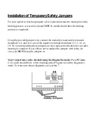


8.
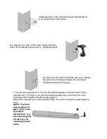
Insert the bracket bushing into the gate mounting bracket.
Inside the black bushing you will see a small bump,
this bump must be facing away from the post to
prevent binding.
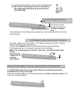
Five Counter Clockwise turns from
end.
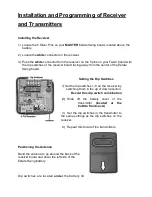
9.
Insert the manual
re-lease key and turn it
5 counter clockwise
turns.
This will position the front fitting on the operator arm in the correct position to fit into the
bracket bushing.
Turn Clockwise to end as a common point of reference.
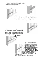
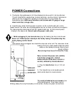
10.
While holding the front fitting in the bracket bushing and gate mounting
bracket, insert the manual release key.
Turn the key
clockwise
until the front fitting reaches the front stop position.
The bracket bushing is now locked in position on the front fitting.
NOTE: The front stop position I S N O T T H E F U L L C L O S E D P O S IT I O N ,
it is the
common point
of reference for
counting
manual turns.
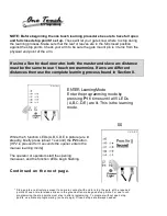
,
3 Turns Counter Clockwise - This is the correct Closed Gate mounting position.
11. NOTE: Returning to the common point of reference during the last step is
important for ac-curacy in this step.
From the front stop position turn the manual release key
counter clockwise 3 turns.
This
will be the mounting position.
Summary of Contents for Sentry Swing
Page 49: ......