www.uponor-usa.com • www.uponor.ca
16
Uponor Climate Co˘ntrol™ - Multifunction Installation Guide
17
The valve relay comes with a set of LEDs to show the relay's status.
Terminal strips for wiring connections to the valve motor and a manual
switch are contained inside the cover. The manual switch, when set to the
Man position, overrides any control signal coming from the Climate Co˘ntrol -
Multifunction controller and allows the installer to set the valve position.
Caution:
Failure to return the manual switch to the auto position
will affect the correct regulation of secondary water temperatures.
When the valve box is connected properly to the control, the
power light turns green. The active light turns red whenever the
control is changing the position of the valve for mixing.
The Climate Co˘ntrol - Multifunction unit supports variable speed injection
mixing, which requires an Uponor Pump Relay Box (A9013030). (See
Pump
Connections
below for additional information on wiring.) Uponor promotes
the use of modulating valves rather than injection pump valves due to lower
power consumption and staying in line with the industry as it moves toward
modulating and condensing boilers.
Pump Connections
Climate Co˘ntrol - Multifunction unit supports on/off operation of pumps
(maximum of three amps) in a variety of applications. Common types of uses
include primary, secondary and domestic hot water (DHW) pumps. As an
added feature, the Climate Co˘ntrol - Multifunction hydronic controller can
be configured to run zone pumps on open or spare ports.
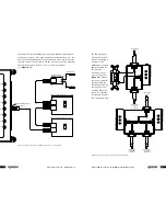
All pumps are quickly and easily connected using Cat5 cables. The Pump
Relay Box comes with LEDs to show the status of the relay. When the relay
and the pump are wired correctly, the auto light will turn green when power
is applied to the circuit. When the system turns on the pump, the Call and
On lights will turn green. A manual switch is included under the top cover
of the relay. When this switch is set to the manual position, the On light will
turn green, provided the auto light is on. When set to the manual position,
the manual switch overrides any control signal coming from the Climate
Co˘ntrol - Multifunction controller and allows the pump to run continuously.
(See
Figure 4-11
.)
Caution:
Failure to return the manual switch to the auto position
can lead to overheating.
Supply-and-return
Dual Sensors (A9013001)
Pump Relay Box (A9013030)
Supply Sensor
Return Sensor
Top View
Auto
Manual
White
Red
Black
Auto
On
Call
Side View
To Climate Co˘ntrol
Main Panel
On
Tx
Run
Rx
Port 1
Input 1
Operate
MMI
Port 8
Input 8
Port 3
Port 2
Port 4
Port 5
Input 2
Input 3
Input 4
Input 5
Port 6
Input 6
Port 7
Input 7
Rx
Tx
Intercon
Figure 4-11:
Typical wiring of a pump or circulator using Pump Relay Box (A9013030)


