12
Flexible Connectors:
If the gas range/oven is connected to a gas supply with a
metal flexible connector, move the range/oven with CAUTION for service or cleaning.
Flexible connectors are not intended for repeated bending. Do not allow
cleaners to make contact with flexible connectors.
The connector and its fittings are designed for use only on the original in-
stallation and are not to be reused for another appliance or at another loca-
tion. Connectors must comply with ANSI Z21.24.
It’s good practice for each household to have an appropriate fire extinguish-
er for use in the event of a house fire.
NOTE:
The instructions appearing in this owner’s guide are not meant to cover
every possible condition and situation that may occur. Common sense and caution
must be practiced when operating and maintaining any appliance.
On sealed burner models never attempt to operate the surface burners with-
out the cooktop, burner caps and ignition wires firmly in place. There is a risk of fire
and/or explosion which could result in personal injury or property loss.
ELECTRICAL GROUNDING INSTRUCTIONS
FOR PERSONAL SAFETY, THIS APPLIANCE MUST BE PROPERLY GROUNDED.
This appliance is equipped with a three-prong grounding plug for your protection
against shock hazard and should be plugged directly into a properly grounded
socket. Do not cut or remove the grounding prong from the plug.
• The gas range must be installed with all electrical connections in accordance with
state and local codes. A standard electrical supply (115 V AC only, 60 Hz), prop-
erly grounded in accordance with the National Electrical Code and local codes
and ordinances is required.
Do not under any circumstances cut or remove the third (ground) prong from the
power plug. Electrical installation should comply with national and local codes.
REPLACEMENT PARTS
Only authorized replacement parts may be used in performing service on the
range. Replacement parts are available from factory authorized parts distributors.
Contact the nearest Unique parts distributor in your area.
Summary of Contents for Prestige UGP-24V PC1 B
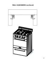
Page 21: ...21 WALL CLEARANCES continued ...
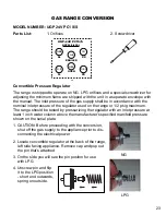
Page 46: ...UGP 24V PC1 S S WIRING DIAGRAM 46 ...
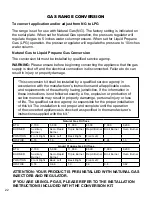
Page 48: ...48 UGP 24V PC1 S S PARTS DIAGRAM AND LIST ...
Page 53: ...NOTES 53 ...


