Unipulse F701+ Operation Manual Download Page 127

120

6


Useful Functions

120

U

se

fu

l F

un

cti

on

s

Chapter

6

 Print count

Set print  count. Also used as an accumulation
count setting even when not in printer mode.

 Year setting (setting mode 7-7)

Set current year. Year between 2000 and 2099
can be set.

 Date setting (setting mode 7-8)

Set current date.

 Time setting (setting mode 7-9)

Set current time.

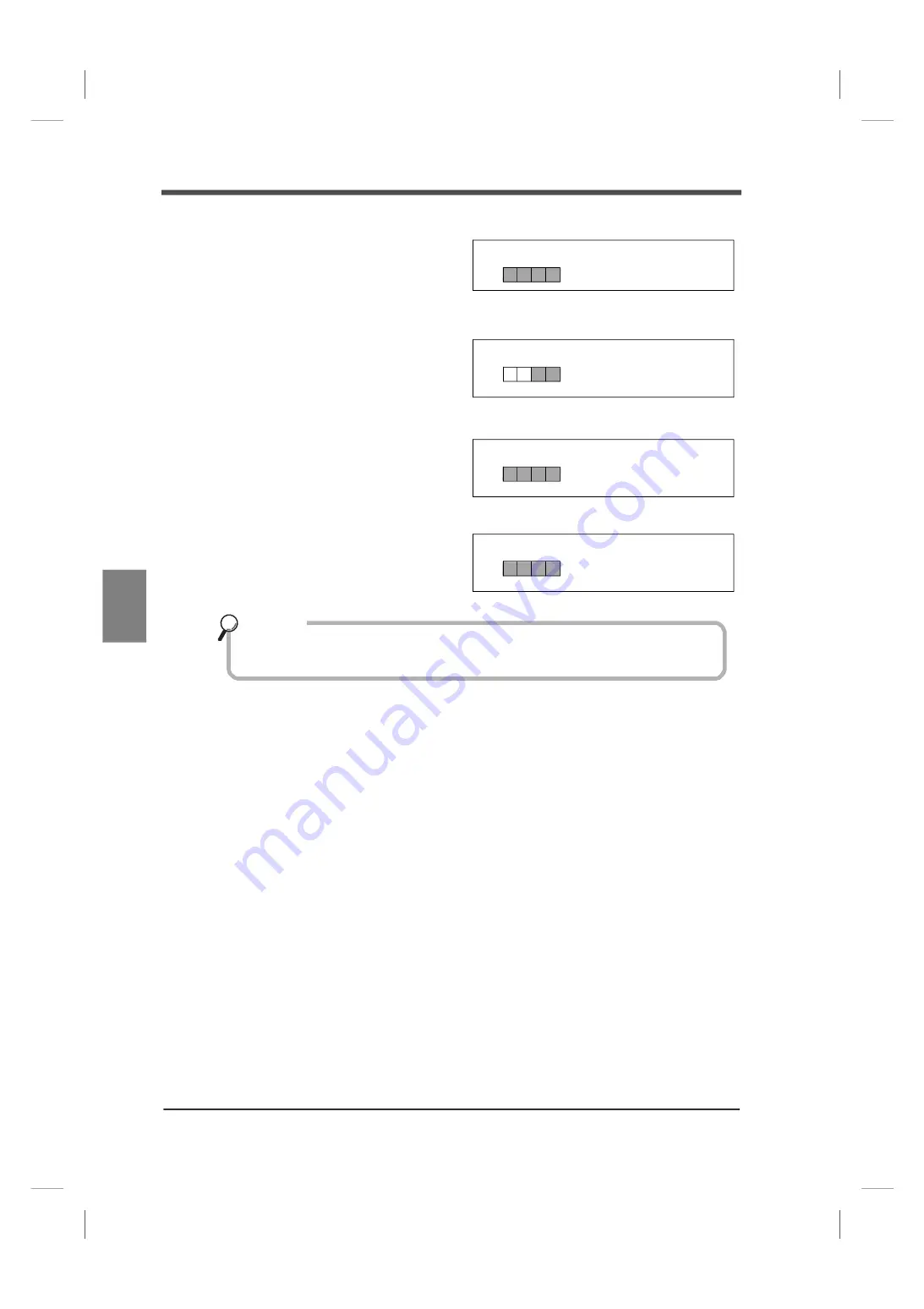
[Print count] (setting mode 7-6)

(Input range: 0 to 9999)

[Print count] (setting mode 7-7)

(Input range: 00 to 99)

0

2

Y Y Y Y

[Date setting] (setting mode 7-8)

(Input range: MM: 01 to 12

M M D D

DD: 01 to 31)

[Time setting] (setting mode 7-9)

(Input range: hh: 00 to 23

h h m m

mm: 00 to 59)

Year, date and time work only when equipped with RS-232C interface for printer
connection (option).

Key point

Summary of Contents for F701+

Page 1: ...01AUG2020REV 1 03 WEIGHING INDICATOR F701 OPERATION MANUAL ...

Page 2: ...ion overview for F701 Basic operation procedures Please read P 13 2 Key Operation Weighing settings Please read P 17 3 Weighing Weighing to fit the purpose Please read P 28 4 Performing Final Discharge Control Other useful functions Please read P 60 6 Useful Functions ...

Page 3: ...cell parallel connection 11 Sensor cable 11 1 12 Protective grounding connection 12 1 13 Frame grounding connection 12 2 Key Operation 13 2 1 Front panel and setting mode configuration chart 13 2 2 How to use the keys 14 How to use the setting keys 14 How to use the one touch keys 14 How to use the designated keys 14 2 3 Selection procedure for the setting mode 15 Specified basic operation of sett...

Page 4: ... 3 5 9 Digital zero DZ Designated key 25 3 5 10 DZ regulation value Setting mode 3 6 26 3 5 11 Gross weight display Net weight display Designated key 26 3 5 12 One touch tare subtraction TARE Dedicated key 26 3 5 13 One touch tare subtraction reset 27 3 5 14 Preset tare subtraction Digital tare subtraction Setting mode 1 9 2 3 27 3 5 15 Limitation of the tare subtraction function Setting mode 4 9 ...

Page 5: ...restoration CASE 2 54 5 7 Sequence control with pause input power failure restoration CASE 3 56 5 8 Sequence control knocking 58 6 Useful Functions 60 6 1 Prohibiting operation of designated keys 60 6 2 Locking changes made to setting values 60 6 3 Checking the option substrate display only 60 6 4 Using the function for setting value restoration 60 6 4 1 Procedures for saving and restoration 60 6 ...

Page 6: ...onverter 104 6 13 3 D A resolution 104 6 14 Using the PROFIBUS interface option 105 6 14 1 Specifications 105 6 14 2 Details for each section 105 6 14 3 Settings related to PROFIBUS 106 6 14 4 Address map 107 6 14 5 Procedures for writing reading and commanding 115 6 15 Connecting a printer 118 6 15 1 Printer mode 118 6 15 2 Printer settings 118 6 15 3 Examples of print format 121 6 16 Using stati...

Page 7: ...ay section 136 9 1 3 Setting section 136 9 1 4 External signal input output 137 9 1 5 Interface standard equipment 137 9 1 6 Interface option 137 9 1 7 General performance 138 9 1 8 Accessories 138 9 2 External dimensions 139 9 3 Block diagram 140 9 4 Compliance with EC Directives 141 ...

Page 8: ...rformed by personnel with electrical knowledge In this manual precautions for safe use of the F701 are described separately as and in the following text The precautions described in this text are important content regarding safety Use this product having understood the content accurately Be sure to read for safety Warning Events that may cause death or severe injury to persons in cases of misuse C...

Page 9: ...en installing the main unit The rating of the AC cable included is AC125V 10A Prepare a separate AC cable if the product is used at a voltage higher than the rating or is used overseas Be sure to check that the power is off before the following actions Removal and installation of optional connectors and so forth Wiring and connection of cables to a terminal block Connection to frame grounding term...

Page 10: ...ot perform parallel wiring and identical wiring Do not use the product if it is damaged Use shielded cables for cables load cell external I O SI F optional interface Avoid a temporary overvoltage exceeding 1500V to be applied to the power source Be sure to allow an interval of five seconds or longer between turning power ON and OFF Use after warming up for 30 minutes or longer following the startu...

Page 11: ...ment and human body The substances are lead mercury cadium hexavalent chromium PBB polybrominated biphenyls PBDE polybrominated diphenyl ethers DEHP bis 2 ethylhexyl phthalate BBP benzyl butyl phthalate DBP dibutyl phthalate and DIBP diisobutyl phthalate 1 5 Package contents The following items are included in the package box Be sure to check the contents before use Foam cushioning material Produc...

Page 12: ... a hole in it 2 Remove installation rails on both sides of the indicator and insert the indicator into the panel F 7 2 0 A F 7 2 0 A Strain gauge type sensor PC PLC PLC DCS etc PLC Recording meters etc D A converter optional RS 485 optional RS 232C optional BCD output optional PROFIBUS optional Printer Display unit Converters Panel cutout size 186 W x92 H mm Unit mm 186 92 Installation panel thick...

Page 13: ...ter 1 3 Insert the installation rails into both sides from the rear of the indicator 4 Tighten securely the clasp on both sides using the included M4 screws Caution Be sure to avoid extreme shock and or vibration when transporting after installing the panel ...

Page 14: ...ver scale and other errors are displayed Refer to P 125 7 1 Over scale display 3 Setting value display 2 Units display The unit can be selected from six setting types N t g kg lb or None 3 Status display Status of the F701 is displayed 4 Setting keys Refer to P 14 How to use the setting keys for details 5 Designated keys Item change is started during setting item display and setting item is confir...

Page 15: ...made by UNIPULSE 5 Connector for external I O signal This connector is used to input and output external signals I O circuits and internal circuits are electrically insulated by photo coupler A compatible connector is 57 30240 manufactured by DDK accessory or equivalent 6 Load cell connector This connector is used to connect load cell A compatible connector is JR16PN 7S manufactured by HIROSE ELEC...

Page 16: ...ff Be sure to check signal names and pin assignment numbers before connecting to the signal I O terminal in order to wire cables properly Be sure to check the wiring and so on carefully before turning the power on Do not touch the signal I O terminal while power is on This may cause electric shock and malfunction The F701 complies with EMC Directives as a product for industrial environments class ...

Page 17: ...ion voltage value near load cell in order to prevent excitation voltage to the load cell from fluctuating cable resistance value from varying due to temperature change Four line type connection As outlined below connect 1 with 2 and 3 with 4 respectively at the terminal block Normal operation appears possible if 2 and 3 of the terminal block are left open however high voltage is placed on the load...

Page 18: ...the cables correctly Caution The F701 excitation voltage is 10V Heat and or breakdown may result if the maximum excitation voltage of a load cell is not 10V or more Be sure to connect EXC and S with EXC and S in case a four line type load cell is used with the F701 Normal operation appears possible if S and S are not connected however high voltage is placed on the load cell which may cause heat an...

Page 19: ...pare a separate AC cable if the product is used at a voltage higher than the rating or is used overseas Be sure to ground the protective grounding Be sure to install and fix the F701 to a panel and so forth Install a breaker so that an operator can turn power OFF immediately and place an appropriate indication showing the breaker installation Warning Connect the product when power is OFF in order ...

Page 20: ...tion P 20 Option substrate P 60 Setting mode 4 DA output mode P 104 DA zero output weight P 104 DA full scale setting P 104 RS 232C RS 485 I F setting P 65 74 ID setting 0000 P 74 Transmission delay time P 75 Extended function selection 1 P 24 Moving average filter P 24 Measurement Act compliance P 27 Setting mode 5 Input selection P 37 Output selection P 37 Restart setting set point 1 P 36 Restar...

Page 21: ...lation value is exceeded GROSS NET key Switch between gross weight and net weight is performed immediately if this key is pressed while the weight value is displayed Net weight display appears if this key is pressed during gross weight display lights up Gross weight display appears if this key is pressed during net weight display lights up CNG ENT key Item change is started during setting item dis...

Page 22: ...alue will flash Selection of setting mode Press the key from 0 to 9 Selection of setting item Switches to the specified after switching to setting mode by performing the above procedure Changes the setting setting mode that corresponds to the setting mode number Use the keys to enter a setting value for each setting item Press the key from 0 to 9 that corresponds to the setting item number kg Curr...

Page 23: ...g Returns to normal display setting mode 0 when the key is pressed while the setting mode number is displayed While changing the setting value after selecting an item press the to skip that item Display returns to showing the setting mode number kg Once the setting is complete the display returns Setting mode number Current setting mode number to show the setting mode number and the current weight...

Page 24: ...e is applied to the sensor 3 2 Load cell junction Multiple load cells can be connected to the F701 by using junction boxes or terminal blocks Single load cell Three load cells 3 Weighing Load cell Rated capacity 10kg Rated output 2mV V Example 1 How do you display 10 000kg Capacity 10 000kg Equivalent calibration 2 0000mV V Hopper F701 Example 2 How do you display 10 000kg Capacity 10 000kg Equiva...

Page 25: ... gravitational acceleration of the region where calibration will be performed Register default zero point Register default zero point Apply a load to the load cell to register the span Set the load cell output value mV V Enable the settings that prohibit calibration Turn ON the LOCK switch on the rear panel to prohibit calibration Setting mode 3 7 Setting mode 3 7 Setting mode 3 2 Setting mode 3 3...

Page 26: ...Setting mode 3 7 Set the common decimal place for displays setting items etc related to weight 3 4 4 Capacity Setting mode 3 2 Set the maximum value weight for use as a scale over scale is displayed if the value set here is exceeded by nine scale divisions The input range is from 1 to 99999 3 4 5 Min scale division Setting mode 3 3 Set the minimum measurement units scale interval The input range i...

Page 27: ...2 Rome 9 8034m s2 Birmingham 9 8127m s2 Kuwait 9 7928m s2 San Francisco 9 7994m s2 Brussels 9 8115m s2 Lisbon 9 8006m s2 Seoul 9 7995m s2 Buenos Aires 9 7970m s2 London 9 8120m s2 Shanghai 9 7946m s2 Kolkata 9 7878m s2 Los Angeles 9 7965m s2 Singapore 9 7804m s2 Cape Town 9 7964m s2 Madrid 9 8021m s2 Stockholm 9 8186m s2 Chicago 9 8030m s2 Manila 9 7836m s2 Sydney 9 7961m s2 Copenhagen 9 8156m s2 ...

Page 28: ...tting mode 9 calibration mode 2 Register the zero point 3 Zero calibration is complete when the weight value display becomes 0 Refer to P 125 7 1 Over scale display in case a calibration error is displayed 3 4 10 Span calibration Actual load calibration Setting mode 9 1 Place weight onto the load cell scale and register the span gain Function selection Setting mode 3 7 0 OFF 1 ON 1 4 scale divisio...

Page 29: ...uting zero calibration kg Balance weight Lights up during calibration and goes out when calibration is complete value set Display during span calibration Equivalent calibration Setting mode 9 2 Input range 0 0001 to 3 2000 Set load cell output Confirm the value value mV V immediately Set the balance weight value below capacity When performing rated value calibration based on the load cell specific...

Page 30: ...adjustments can be made manually 3 5 3 Analog low pass filter Setting mode 2 6 This is a low pass filter that simultaneously removes noise content from the input signal of the load cell and averages the analog signal to stabilize the weight value 3 5 4 Digital low pass filter Setting mode 2 6 This filter screens the A D converted data and cancels unnecessary noise Like the low pass filter of an an...

Page 31: ...gle setting range Compared point 1 second before 0 95 second before 0 8 second before 0 6 second before and 0 3 second before Checker mode The stable signal immediately turns OFF if the difference between the weight value and the current weight value exceeds even a single setting range Compared point 0 09 second before 0 06 second before and 0 3 second before A D 500 times sec 1 time 512 times A D...

Page 32: ...ds DZ regulation value cannot be zeroed 1 Press the key once 2 Gross weight GROSS becomes zero Perform the following procedure if digital zero operation is carried out when gross weight is larger than the DZ regulation value Weight value equivalent to DZ regulation value is subtracted and flashes to warn error Zero tracking Setting mode 2 8 Duration 0 0 to 9 9 seconds Change range from zero point ...

Page 33: ...action Digital tare subtraction Setting mode 1 9 2 3 for details regarding preset tare subtraction 3 5 12 One touch tare subtraction TARE Dedicated key This is a function that equalizes gross weight and tare weight and then zeros net weight 1 Press the key 2 One touch tare subtraction is complete and lights up The following causes are assumed when the net weight does not become zero even if tare s...

Page 34: ...n function 3 5 15 Limitation of the tare subtraction function Setting mode 4 9 Limitation can be imposed on the operation of preset tare weight and one touch tare subtraction 3 5 16 Tare weight display Designated key This is a function that displays current tare weight The tare weight that is displayed here is the result including the one touch tare subtraction and preset tare weight This is displ...

Page 35: ...ition Compares regularly Starts comparison after the start signal is input SP1 Turns ON when the condition is met Turns ON after the start signal is input and turns OFF after the condition is met SP2 Turns ON when the condition is met Turns ON after the start signal is input and turns OFF after the condition is met SP3 Turns ON when the condition is met Turns ON after the start signal is input and...

Page 36: ... setting P 48 5 3 Sequence control with adjust feeding P 50 5 4 Sequence control with external judging P 52 5 5 Sequence control with pause input power failure restoration CASE 1 in the event of a power outage Selecting a discharge procedure Select the feeding discharging control Select simple comparison sequence mode Select the net and gross weight Make selections for weighing comparison and judg...

Page 37: ...tion regulation value 0 100 Auto free fall coefficient 2 4 Value added to subtracted from compensation setting value Sum of accumulated value of weighing errors Number of times for auto free fall Auto free fall coefficient Weighing times Actual weighing value Weighing error Number of times for auto free fall Compensation 1 20 050 0 050 1 0 500 2 20 040 0 040 2 0 500 3 20 070 0 070 3 0 500 4 20 080...

Page 38: ...t to zero times no judging Set the number of times for judging to once or more when using auto free fall compensation function Values of number of times for auto free fall and free fall compensation counter become 0 when compensation setting value is changed Auto free fall coefficient can be selected from 1 4 2 4 3 4 and 1 Select 1 for weighing where the weighing value remains nearly the same ever...

Page 39: ...r Upper lower limit Setting mode 0 1 0 2 Input range 0 to 99999 Weighing function 1 Setting mode 2 1 2 Comparison OFF 1 Net weight 0 Gross weight Upper lower limit comparison Weighing function 2 Setting mode 2 2 1 Compare when external judging input is ON 0 Compare regularly Upper lower limit comparison mode When comparison OFF is selected the external output signals for upper lower limit and over...

Page 40: ...hen weighing is complete Determine the timing to output the complete signal in complete signal output mode Comparison inhibit time 1 judging time Input range 0 00 to 9 99 Setting mode 1 1 1 2 1 8 comparison inhibit time 2 0 Final set point 1 Final set point 2 Final compensation Comparison inhibit time 1 Judging time Comparison inhibit time 2 Complete output time Setting mode 1 3 Input range 0 00 t...

Page 41: ...he weighing value to zero by performing digital zero if the weighing value is gross weight and by performing tare subtraction if the value is net weight 00 No auto zero Auto zero is not performed 01 Auto zero is performed every time 02 Auto zero is performed once every two weighings 03 Auto zero is performed once every three weighings 99 Auto zero is performed once every 99 weighings Number of tim...

Page 42: ...n ON is selected set the time to perform adjust feeding after weighing complete 4 8 6 Number of times for knocking knocking time Set the duration for which and number of times that the knocking output repeatedly turns ON and OFF after SP3 is turned ON What is knocking In order to shake off residue inside a tank a fixed number of times and duration for the pulse can be output from the external sign...

Page 43: ... 3 for the timing chart Area indicates the range of the weighing setting of SP1 SP2 and SP3 SP1 set point 1 area The weight value of 1 SP2 set point 2 area The weight value of 2 1 SP1 set point 1 area The weight value of 3 2 Restart setting Setting mode 5 3 5 4 5 5 Input range 0 to 100 SP1 range Setting mode 5 3 SP2 range Setting mode 5 4 SP3 range Setting mode 5 5 when weighing 100 00 kg Weighing...

Page 44: ...tion 16 IN Input selection 3 5 IN Input selection 5 17 IN Input selection 4 6 OUT Near zero 18 OUT Lower limit 7 OUT SP1 19 OUT Upper limit 8 OUT SP2 20 OUT Stable 9 OUT SP3 21 OUT Output selection 1 10 OUT Under 22 OUT Output selection 2 11 OUT Over 23 OUT Output selection 3 12 COM sink type 24V RTN source type 24 COM sink type 24V RTN source type Top view 121110 9 8 7 6 5 4 3 2 1 242322212019181...

Page 45: ...lay contact Transistor 12V IN IN TTL open collector output F701 Open circuit OFF Short circuit ON Do not apply voltage to the signal input circuit from outside The external element must be an element in which Ic 10mA or more can be applied External element leak must be 100μA or below ON when IN is H No 2 to 5 14 to 17 No 12 24 approx 6mA Vcc Inside COM F701 Prepare an external power supply for the...

Page 46: ... must be connected when connecting transistors photo couplers etc 4 9 4 External input signal There are edge input and level input for external input Edge input Switch processes at ON edge OFF ON or OFF edge ON OFF of external input When processing at ON edge OFF ON Output Input COM F701 Source type PLC etc 24VRTN 24V 24VRTN No 1 13 No 6 to 11 18 to 23 No 12 24 F701 DC24V Push Toggle switch switch...

Page 47: ...dge input Reset tare subtraction mentioned above at ON edge However tare setting is not released Accumulation command Edge input Cumulatively adds up the weight value and counts up the number of times at ON edge The target to add the weight value to depends on the final and over under comparison weight The negative weight value is neither added nor counted up Feeding discharging Level input This s...

Page 48: ...o comparison is made when external judging input is ON during sequence mode weighing is completed with over under comparison at ON edge after operation of complete signal output mode Pause Edge input This signal is enabled when sequence mode is set to restoration ON Weighing is paused at ON edge Total print Edge input Prints and clears the accumulated data at ON edge However an RS 232C interface o...

Page 49: ...s on complete output time When judging is OFF Complete output turns ON in the event of OFF edge of SP3 signal ignoring setting of complete signal output mode The timing with which output turns ON depends on complete output time Near Zero Output turns ON when weight value selected in near zero comparison mode near zero setting value with comparison set to compare regularly only Stable Output turns ...

Page 50: ...n seq error Refer to P 126 7 2 Sequence error display for details regarding seq error RUN Output turns ON when normal operation is performed Paused Output turns ON when paused Waiting for judging input Output turns ON while waiting for judging input when comparison is made when external judging input is ON during sequence mode Knocking Output turns ON during knocking operation if number of times f...

Page 51: ...Set point 2 Final Compensation Final NET Time SP1 㸦output㸧 SP2 㸦output㸧 SP3 㸦output㸧 Comparison inhibit timer Judging timer Stable 㸦output㸧 Over 㸦output㸧 t0 t1 t2 Near zero 㸦output㸧 Over Under 1 2 3 5 Complete timer t3 Complete 㸦output㸧 Go 㸦output㸧 Under 㸦output㸧 ON OFF ON ON ON ON ON OFF ON No 2 No 1 No 3 No 4 No 5 No 6 No 7 4 No 8 No 9 25 of final 6 7 t0 comparison inhibit time 1 t1 comparison i...

Page 52: ...ue compensation setting value 6 Operation of the judging timer Setting mode 1 2 judging time t2 7 Output of complete signal and output of judging signal HI GO or LO lights up Setting mode 0 7 over Setting mode 0 8 under Setting mode 0 9 final Setting mode 1 3 complete output time t3 Setting mode 2 1 final and over under comparison Setting mode 2 2 output selection 22 pin Setting mode 2 2 over unde...

Page 53: ...art 㸦input㸧 SP1 㸦output㸧 SP2 㸦output㸧 SP3 㸦output㸧 Comparison inhibit timer Judging timer Complete timer Judging 㸦output㸧 㸦Over go or under㸧 t0 t1 t2 t3 Hold Restart 㸦input㸧 Over Under No 2 No 1 No 3 No 4 No 6 No 5 No 7 No 9 No 10 No 11 t3 No 12 No 8 1 2 3 4 5 t0 comparison inhibit time 1 t1 comparison inhibit time 2 t2 judging time t3 complete output time SP1 set point 1 SP2 set point 2 SP3 set p...

Page 54: ...etting mode 1 8 comparison inhibit time t1 8 Final compensation net weight SP3 light goes out Setting mode 0 6 compensation Setting mode 0 9 final Setting mode 2 1 final and over under comparison Set point 3 9 pin OFF 3 Set point 3 output is OFF when compared weight value final setting value compensation setting value 9 Operation of the judging timer Setting mode 1 2 judging time t2 10 Output of c...

Page 55: ...ut㸧 㸦Over or go㸧 t2 t3 Hold t2 Comparison inhibit timer t0 Adjust feeding timer Final Compensation Over Under Tare subtraction 㸦input㸧 Start 㸦input㸧 SP1 㸦output㸧 SP2 㸦output㸧 SP3 㸦output㸧 No 2 No 1 No 3 No 4 No 6 No 5 No 7 No 9 No 10 No 12 No 8 No 13 1 2 3 4 6 t1 t4 5 No 9 t0 comparison inhibit time 1 t1 comparison inhibit time 2 t2 judging time t3 complete output time SP1 set point 1 SP2 set poin...

Page 56: ...ing if adjust feeding selection in setting mode 2 4 sequence mode is 1 Adjust feeding ON Judged to be under and switches to No 10 sequence when compared weight final setting value under setting value Switches to No 12 sequence when compared weight final setting value under setting value 10 Operation of the adjust feeding timer SP3 lights up Setting mode 1 4 adjust feeding time Set point 3 9 pin ON...

Page 57: ...2 Waiting for external judging 㸦output㸧 Comparison inhibit timer t0 t1 Flashes Status display Final Compensation Over Under t1 Tare subtraction Start 㸦input㸧 SP1 㸦output㸧 SP2 㸦output㸧 SP3 㸦output㸧 No 2 No 1 No 3 No 4 No 6 No 5 No 7 No 9 No 10 No 12 No 11 No 14 No 8 No 13 1 2 3 6 4 5 7 4 Over go or under 㸦input㸧 t0 comparison inhibit time 1 t1 comparison inhibit time 2 t2 judging time t3 complete o...

Page 58: ... anything other than GO the displayed result will blink and a waiting for external judging signal will turn ON signal for over under comparison result will also turn ON Switches to No 12 sequence if over under comparison result is GO 6 Judged to be under when compared weight value final setting value under setting value Judged to be over when compared weight value final setting value over setting ...

Page 59: ...arison inhibit timer Judging timer Complete 㸦output㸧 Judging 㸦output㸧 㸦Over go or under㸧 t1 t0 t2 t3 Hold Pause 㸦input㸧 Stable 㸦output㸧 Restart setting SP1 80 Final SP1 0 8 Over Under No 2 No 1 No 3 No 4 No 5 Paused 㸦output㸧 No 6 No 7 No 8 No 9 No 10 No 11 No 12 No 13 No 14 1 2 3 4 5 6 7 8 With power failure restoration the operation restarts on start input t0 comparison inhibit time 1 t1 comparis...

Page 60: ...nt 1 output is OFF when compared weight value final setting value set point 1 setting value 7 Operation of the comparison inhibit timer Setting mode 1 1 comparison inhibit time t0 8 Final set point 2 net weight value SP2 light goes out Setting mode 0 5 set point 2 Setting mode 0 9 final Setting mode 2 1 final and over under comparison Set point 2 8 pin OFF 5 Set point 2 output is OFF when compared...

Page 61: ...ting SP1 80 Final SP1 0 8 Final Compensation Over Under Tare subtraction 㸦input㸧 Start 㸦input㸧 SP1 㸦output㸧 SP2 㸦output㸧 SP3 㸦output㸧 Comparison inhibit timer Judging timer Complete 㸦output㸧 Judging 㸦output㸧 㸦Over go or under㸧 Pause 㸦input㸧 Stable 㸦output㸧 Paused 㸦output㸧 No 2 No 1 No 3 No 4 1 No 5 2 3 4 5 6 7 No 6 No 7 No 8 No 9 No 10 No 11 No 12 8 t0 comparison inhibit time 1 t1 comparison inhib...

Page 62: ...alue final setting value set point 1 setting value In the chart the OFF condition is met through set point 1 of restart setting 6 Final set point 2 net weight value SP2 goes out Setting mode 0 5 set point 2 Setting mode 0 9 final Setting mode 2 1 final and over under comparison Set point 2 8 pin OFF 5 Set point 2 output is OFF when compared weight value final setting value set point 2 setting valu...

Page 63: ...㸧 SP1 㸦output㸧 SP2 㸦output㸧 SP3 㸦output㸧 Comparison inhibit timer Judging timer Complete 㸦output㸧 Judging 㸦output㸧 㸦Over go or under㸧 Pause 㸦input㸧 Stable 㸦output㸧 Adjust feeding timer Paused 㸦output㸧 No 2 No 1 No 3 No 4 1 No 6 2 3 No 5 No 7 No 8 5 No 9 4 No 10 No 11 No 12 6 8 No 13 No 14 9 7 10 With power failure restoration the operation restarts on start input t0 comparison inhibit time 1 t1 co...

Page 64: ...lity 5 The following restrictions apply to each of the control output statuses when restarting Restarting does not take place when the previous set point 3 was in OFF status because either the weighing has already completed or weighing has not yet started Set point 3 output turns ON in the following condition weight value at restart final compensation restart setting set point 3 when set point 3 i...

Page 65: ... t2 t3 Comparison inhibit timer t0 Final Compensation Over Under Tare subtraction 㸦input㸧 Start 㸦input㸧 SP1 㸦output㸧 SP2 㸦output㸧 SP3 㸦output㸧 t1 Knocking timer t4 Knocking 㸦output㸧 t4 3 5 4 2 1 First time Third time Second time 6 t0 comparison inhibit time 1 t1 comparison inhibit time 2 t2 judging time t3 complete output time t4 knocking time SP1 set point 1 SP2 set point 2 SP3 set point 3 ...

Page 66: ...eight value final setting value compensation setting value 9 Operation of the knocking timer Setting mode 5 2 output selection 23 pin Setting mode 5 6 number of times for knocking Setting mode 5 7 knocking time t4 Output selection knocking output 23 pin ON 4 While the knocking timer is running the knocking output repeatedly turns OFF ON in accordance with the number of times set 10 Operation of th...

Page 67: ...ate has been mounted 1 will be displayed 6 4 Using the function for setting value restoration The current setting value value registered for restoration can be saved The saved value can be restored 6 4 1 Procedures for saving and restoration Saving a setting value Input 3964 in setting mode 9 9 to save the current setting value as the setting value for restoration Restoring a setting value Input 3...

Page 68: ...ending on time of purchase NOV RAM check is not performed when the lock switch on the rear panel is ON Confirm the display unit by visual check Check stops when there is a memory check error If check stops or the display unit does not display information correctly it is a sign of failure Repair can be performed at UNIPULSE or at the point of purchase Memory clear Performs a self check after cleari...

Page 69: ...apter 6 6 8 Replacing the I O substrate The I O substrate can be replaced To replace the I O substrate remove the two M3 screws 1 pull out the whole control panel and then replace After replacement retighten the M3 screws 1 1 M3 screw 1 M3 screw ...

Page 70: ...units connected to SI F In sequence mode Outputs a command when the judging signal GO OVER UNDER turns ON Therefore automatic print commands will not be output when it is set to no judging judging times 00 In simple comparison mode Outputs a command when the complete signal turns ON Therefore the automatic print command will not be output when final and over under comparison are set to compare OFF...

Page 71: ... from none odd or even Code ASCII Connector pin assignment Cables Use a cross type cable if the cable is connected to a DTE data terminal device PC and so on and a straight type cable if connected to a DCE data circuit terminator modem and so on Below are examples of using cross cables Compatible connector 9 pin D SUB connector DE 09SN manufactured by JAE XM2D 0901 manufactured by OMRON and so on ...

Page 72: ...ation mode 2 Transmits net weight continuously Ignores all R W and C commands Communication mode 3 Transmits gross weight and net weight continuously Ignores all R W and C commands Settings for RS 232C I F setting mode 4 4 Terminator Stop bit 6 Printer mode 5 115 2kbps 4 57600 bps 3 38400 bps 2 19200 bps 1 9600 bps 0 4800 bps Baud rate selection 7 Communication mode 6 6 Communication mode 5 5 Comm...

Page 73: ... 6 10 4 Transmission format for details on the transmission format and P 63 Automatic print command for details on the automatic printing function Attention Timing of continuous transmission When transmission mode 1 2 or 3 is selected the remote continuous transmissions are as follows according to the communication baud rate settings Communication baud rate Remote continuous transmission 115 2k bp...

Page 74: ...mparison OFF Priority N H or L 0 1 2 3 4 5 6 7 8 9 10 11 12 13 14 15 16 18 19 G S 1 2 3 4 CR LF HEADER 5 digit gross weight decimal point Sign or 17 0 1 2 3 4 5 6 7 8 9 10 11 12 13 14 15 16 17 18 19 N T 1 2 3 4 CR LF HEADER 5 digit net weight decimal point Sign or 0 1 2 3 4 5 6 7 8 9 10 11 12 13 14 15 16 17 18 19 20 21 22 W T 1 2 3 4 HEADER 5 digit net weight Sign gross weight or 5 digit gross wei...

Page 75: ... 0 CR LF R CR B Host F701 R C 1 0 0 0 0 CR LF R CR C Host F701 R CR R D 0 0 0 0 CR 0 LF D 0 0 1 ON 0 OFF Tare subtraction 1 ON 0 OFF Weight value stable 0 OFF 1 ON Weight value HOLD 1 ON 0 OFF 1 Net weight 0 Gross weight Weight display 1 OFF 1 ON Weight value zero error Undefined Rear terminal LOCK Host F701 R CR R E 0 0 0 0 CR 0 LF E 0 0 1 ON 0 OFF Under output signal 1 ON 0 OFF SP3 signal 0 OFF ...

Page 76: ... zero output signal 0 OFF 1 ON Lower limit output signal Undefined Host F701 R CR R G 0 0 0 0 CR 0 LF G 0 0 Operating mode 0 OFF 1 ON Weight error output signal 0 or 1 to 5 0 or 2 to 9 Calibration error 0 OFF 1 ON Error output signal Undefined Sequence error in sequence error 3 SPAN calibration 2 ZERO calibration 1 Weighing 0 Weight value overflow 5 LOAD 4 LOAD 3 OFL1 2 OFL2 1 OFL1 0 Host F701 R C...

Page 77: ...read R CR J R CRLF J 1 0 0 0 0 0 R CR J R CR LF J Host F701 W W CR CR Setting value No 5 digit setting value no decimal point LF Setting value No 1 2 1 2 1 0 0 0 0 Host F701 W CR Setting value No 5 digit setting value LF No return data no decimal point 1 2 1 0 0 0 0 Host F701 C CR E No return data Host F701 C CR 0 0 0 0 CR 0 LF A 0 N A 0 Calibrating 0 Normal end 2 to 9 Error same as error display ...

Page 78: ...ng 0 W CR LF 1 6 LOCK2 to prohibit writing W CR LF 1 7 LOCK2 to prohibit writing 0 0 W CR LF 2 0 LOCK2 to prohibit writing 0 0 W CR LF 2 1 LOCK2 to prohibit writing 0 0 W CR LF 2 2 LOCK1 to prohibit writing W CR LF 2 3 LOCK1 to prohibit writing W CR LF 2 4 LOCK1 to prohibit writing W CR LF 2 5 LOCK1 to prohibit writing W CR LF 2 6 LOCK2 to prohibit writing 0 0 0 W CR LF 2 7 LOCK2 to prohibit writi...

Page 79: ...nd LOCK SW to prohibit writing 0 W CR LF 4 8 LOCK2 to prohibit writing W CR LF 4 9 LOCK2 to prohibit writing 0 W CR LF 5 0 LOCK2 to prohibit writing 0 0 0 W CR LF 5 1 LOCK2 to prohibit writing W CR LF 5 2 LOCK2 to prohibit writing W CR LF 6 0 LOCK2 to prohibit writing W CR LF 6 1 LOCK2 to prohibit writing 0 0 0 0 W CR LF 6 2 LOCK2 to prohibit writing 0 0 W CR LF 6 3 LOCK2 to prohibit writing 0 0 W...

Page 80: ...Select from CR CR LF Communication mode Hand shake Modbus RTU Selection code Binary Modbus RTU ASCII UNI Format 6 11 2 RS 485 connection Two wire point to point Use twisted pair wires for connection cables Noise margin increases However two core parallel cables are sufficient for short distance connection SG terminal is a ground terminal which protects circuits used on the circuit SG terminal does...

Page 81: ...performed using start and end commands normal communication is not possible due to output collision if only start commands are transmitted to multiple devices If the ID no is 0000 the device will be able to transmit receive from the moment the power is turned ON Therefore be sure to set an ID no other than 0000 when connecting multiple devices A B A B A B A B Twisted pair wires F701 F701 F701 F701...

Page 82: ...04 Read Input Register Read input register 05 0x05 Write Single Coil Write to single coil 06 0x06 Write Single Register Write to single holding register 15 0x0F Write Multiple Coils Write to multiple coils 16 0x10 Write Multiple Registers Write to multiple holding registers 08 0x08 Diagnostics Diagnostic mode 11 0x0B Get Comm Event Counter Read event counter 12 0x0C Get Comm Event Log Read communi...

Page 83: ...l status is 0 at all times The process is carried out as soon as the command is read Consider execution confirmation of the coil to be something that is completed by a normal response from the function code 05 0x05 Write Signal Coil or 15 0x0F Write Multiple Coils Request Function 1 byte 0x01 Start address 2 bytes 0x0000 to 0xFFFF Number of coils 2 bytes 1 to 2000 0x07D0 Response Function 1 byte 0...

Page 84: ... initial address 11101000 0xE8 represented in binary digits The status can also be read by function code 04 0x04 Read Input Registers In function code 04 the status can be read along with the weight value Request Function 1 byte 0x02 Start address 2 bytes 0x0000 to 0xFFFF Number of inputs 2 bytes 1 to 2000 0x07D0 Response Function 1 byte 0x02 Data bytes 1 byte N Input status n bytes N or N 1 Error...

Page 85: ...ings for this example are as follows In function code 03 only the LO words or the HI words are read when the start address specifies the LO words from a 32 bit integer data area or the end of the start address number of registers specifies HI words from a 32 bit integer data area Request Function 1 byte 0x03 Start address 2 bytes 0x0000 to 0xFFFF Number of registers 2 bytes 1 to 125 0x7D Response ...

Page 86: ...ess specifies the LO words from a 32 bit integer data area or the end of the start address number of registers specifies HI words from a 32 bit integer data area Request Function 1 byte 0x04 Start address 2 bytes 0x0000 to 0xFFFF Number of registers 2 bytes 1 to 125 0x7D Response Function 1 byte 0x04 Data bytes 1 byte 2 x N Register value N x 2 bytes Error response Error code 1 byte 0x84 Function ...

Page 87: ...ng ON the GROSS display address 00001 Note that the relative address is 0x00 when writing in GROSS display The response in the case of being written in normally is the same as request Consider execution confirmation of the coil to be something that is completed by a normal response Request Function 1 byte 0x05 Start address 2 bytes 0x0000 to 0xFFFF Output data 2 bytes 0x0000 or 0xFF00 Response Fun...

Page 88: ...ing in compensation The response in the case of being written in normally is the same as request In function code 06 be sure to write in a 16 bit integer data after address 40057 If the start address specifies a 32 bit integer data area an error response will be returned Request Function 1 byte 0x06 Start address 2 bytes 0x0000 to 0xFFFF Output data 2 bytes Response Function 1 byte 0x06 Start addr...

Page 89: ...on of the coil to be something that is completed by a normal response Do not execute commands in the address combinations listed below When executed commands will be carried out one by one but may not operate properly Addresses 00001 and 00002 Addresses 00009 and 00010 Addresses 00003 to 00006 Addresses 00011 to 00013 Addresses 00007 and 00008 Request Function 1 byte 0x0F Start address 2 bytes 0x0...

Page 90: ...ion feeding time address 40065 to 100 0x0064 Note that the relative address is 0x40 when writing in the complete output time Request Function 1 byte 0x10 Start address 2 bytes 0x0000 to 0xFFFF Number of registers 2 bytes 0x0001 to 0x0078 120 Number of bytes 1 byte 2 x N Changed data N x 2 bytes Response Function 1 byte 0x10 Start address 2 bytes 0x0000 to 0xFFFF Number of registers 2 bytes 0x0001 ...

Page 91: ...eads this counter before and after a request to judge whether the process has been executed or not The status is generally 0x0000 when the slave device is not busy Example Reading the event counter In the example the slave device is not busy 0x0000 and has processed a total of 264 0x0108 commands Request Function 10 Response Function 10 Start address HI 00 Start address HI 00 Start address LO 08 S...

Page 92: ... status The example shows 264 times for the event counter 0x0108 289 times for the message counter 0x0121 and not busy 0x0000 The newest event is 11000000 0xC0 and bit 6 is 1 which means that the broadcast was received The previous event is 00 indicating that the slavedevice received a request for Communications Restart Request Function 1 byte 0x0C Response Function 1 byte 0x0C Byte count 1 byte N...

Page 93: ...nsmit exception code 1 to 3 1 Transmit exception code 4 2 0 3 0 4 Transmit write in time out 5 Listen Only Mode 0 for F701 6 1 7 0 Slave is in Listen Only Mode 04 is recorded for Listen Only Mode Communication is initialized by Communication Restart This event is recorded when communication restarts Event is 00 If the slave device is in Continue on Error mode the event is written in the existing l...

Page 94: ...functions The slave device responds by returning the received request frame except when there is an error Also all counters for diagnosis are cleared when the power is turned ON Request Function 1 byte 0x11 Response Function 1 byte 0x11 Number of bytes 1 byte Slave ID 1 byte RUN Indicator 1 byte 0x00 Weight error or calibration error 0xFF Normal Additional information 3 byte Version Error response...

Page 95: ...agnostic Register Request echo 03 0x0003 Change ASCII Input Delimiter 04 0x0004 Force Listen Only Mode Receive only mode 05 to 09 Unused 10 0x000A Clear Counters and Diagnostic Register Clear counters and registers 11 0x000B Return Bus Message Count Read message count 12 0x000C Return Bus Communication Error Count Read CRC error count 13 0x000D Return Bus Exception Error Count Read exception error...

Page 96: ...ters and diagnostic registers are cleared 11 0x000B Return Bus Message Count The total number of frames detected by a slave device is read These are counted when the slave ID matches or when a message is transmitted simultaneously to all devices Request Function 1 byte 0x08 Sub function 2 bytes 0x00 0x02 Data N x 2 bytes Arbitrary 16 bit data Response Request echo Request Function 1 byte 0x08 Sub ...

Page 97: ...est Function 1 byte 0x08 Sub function 2 bytes 0x00 0x0C Data 2 bytes 0x00 0x00 Response Function 1 byte 0x08 Sub function 2 bytes 0x00 0x0C Data 2 bytes CRC error count Request Function 1 byte 0x08 Sub function 2 bytes 0x00 0x0D Data 2 bytes 0x00 0x00 Response Function 1 byte 0x08 Sub function 2 bytes 0x00 0x0D Data 2 bytes Exception response count Request Function 1 byte 0x08 Sub function 2 bytes...

Page 98: ...s read 20 0x0014 Clear Overrun Counter and Flag The overrun counter is cleared and the error flag is dropped Request Function 1 byte 0x08 Sub function 2 bytes 0x00 0x11 Data 2 bytes 0x00 0x00 Response Function 1 byte 0x08 Sub function 2 bytes 0x00 0x11 Data 2 bytes Busy Request Function 1 byte 0x08 Sub function 2 bytes 0x00 0x12 Data 2 bytes 0x00 0x00 Response Function 1 byte 0x08 Sub function 2 b...

Page 99: ...n of the 32 bit variable or the start address number of registers includes the LO position of 32 bit Function codes 3 6 and 16 Exception code 03 Specified data is out of range Confirm that the number of coils statuses or registers are within readable range Function codes 1 to 4 Confirm that the output value is 0x0000 or 0xFF00 Function code 5 Confirm that the output value is from 0x0000 to 0xFFFF ...

Page 100: ...nd in the following cases When the specified slave address no and the actual address do not match When the error check code does not match When communication errors such as parity errors are detected When there is a spacing of 1 5 characters or more in the frame configuration data When the slave address no is set to 0 Key point ...

Page 101: ...xternal judging ON 00016 to 00018 Backup not allocated 00019 Zero calibration 00020 Span calibration actual load calibration 00021 Span calibration equivalent calibration 00022 to 09999 Reserved area cannot be used Data type Address Data name Data format Discrete input 1XXXX 10001 HI LIM 1 bit 10002 LO LIM 10003 HI 10004 GO 10005 LO 10006 SP1 10007 SP2 10008 SP3 10009 NEAR ZERO 10010 PAUSE 10011 W...

Page 102: ... limit LO 40013 Near zero HI 40014 Near zero LO 40015 Weighing function 2 HI 40016 Weighing function 2 LO 40017 Tare setting HI 40018 Tare setting LO 40019 Balance weight value HI 40020 Balance weight value LO 40021 Capacity HI 40022 Capacity LO 40023 Net over HI 40024 Net over LO 40025 Gross over HI 40026 Gross over LO 40027 Compensation for gravitational acceleration HI 40028 Compensation for gr...

Page 103: ...of times for judging 40069 Weighing function 1 40070 Weighing function 3 40071 Sequence mode 40072 Function key inhibited 40073 Filter 40074 MD time range 40075 ZT time range 40076 DZ regulation value 40077 Function selection 40078 D A output mode 40079 Moving average filter 40080 Measurement Act compliance 40081 Output selection 40082 Restart setting Set point 1 40083 Restart setting Set point 2 ...

Page 104: ...he over signal of the indicator GO Indicates the status of the go signal of the indicator LO Indicates the status of the under signal of the indicator SP1 Indicates the status of the SP1 signal of the indicator SP2 Indicates the status of the SP2 signal of the indicator SP3 Indicates the status of the SP3 signal of the indicator NEAR ZERO Indicates the status of the near zero signal of the indicat...

Page 105: ...Indicates over 0 to 999 Under Indicates under 0 to 999 Comparison inhibit time Indicates comparison inhibit time 0 to 999 Judging time Indicates judging time 0 to 999 Complete output time Indicates complete output time 0 to 999 Compensation feeding time Indicates compensation feeding time 0 to 999 AZ times Indicates the number of times for AZ 0 to 99 Number of times for judging Indicates judging t...

Page 106: ...tion 3 Status 2 4 Status 3 Undefined Undefined Undefined OFL2 LOAD LOAD ZALM Calibration process status Calibration error 0 to 9 Sequence error 0 to 9 15 14 13 12 11 10 9 8 7 6 5 4 3 2 1 0 Undefined COMPL Undefined Waiting for judgment Pause NZ SP3 SP2 SP1 LO HI LIM 15 14 13 12 11 10 9 8 7 6 5 4 3 2 1 0 Undefined Undefined GO HI LO LIM RUN LOCK2 LOCK1 LOCK ZT NET TARE HOLD Stable Unit Decimal poin...

Page 107: ...negative value 6 MD ZT time range Units Bit No 4 3 2 None 0 0 0 kg 0 1 1 t 0 0 1 g 0 1 0 lb 1 0 0 N 1 0 1 Decimal place Bit no 1 0 None 0 0 0 0 0 1 0 00 1 0 0 000 1 1 Weight data HI 31 30 29 28 27 26 25 24 23 22 21 20 19 18 17 16 15 14 13 12 11 10 9 8 7 6 5 4 3 2 1 0 Undefined 1 4 scale division CZ 1 4 scale division Over Sign Weight data LO Address N HI Address N 1 LO Undefined Undefined Time 15 ...

Page 108: ...switches andso on and non contacts transistors TTL open collector output and so on Compatible connector 57 30360 manufactured by DDK accessory or equivalent 1 COM 19 COM 2 OUT 1 20 OUT 20000 3 OUT 2 21 OUT 40000 4 OUT 4 22 OUT 80000 5 OUT 8 23 OUT MINUS 6 OUT 10 24 OUT OVER 7 OUT 20 25 OUT P C 8 OUT 40 26 OUT STROBE 9 OUT 80 27 IN Data hold 10 OUT 100 28 IN Logic switch 11 OUT 200 29 IN Output sel...

Page 109: ...ts 1 over when the weight value being output as BCD data satisfies the following conditions Digit data 8 4 2 1 0 0 0 0 0 1 0 0 0 1 2 0 0 1 0 3 0 0 1 1 4 0 1 0 0 5 0 1 0 1 6 0 1 1 0 7 0 1 1 1 8 1 0 0 0 9 1 0 0 1 Weight value Conditional equation Net weight NET Net weight Setting value for net over Gross weight GROSS Gross weight Setting value for gross over Tare TARE Tare 99999 over digit F701 Insi...

Page 110: ...speed may be too fast to read In such cases set the data update rate to be longer fewer times 6 12 9 Data hold input When this input terminal is short circuited to the COM terminal the BCD data is held Also strobe pulse will not be output 6 12 10 Logic switch input Select the logic of output signals On open circuit negative logic On short circuit positive logic 6 12 11 Output selection input Selec...

Page 111: ...put mode Test mode is used when making fine adjustments to zero gain D A zero output weight value Set the weight value which outputs 4mA The default value is 0 D A full scale setting Set the range for weight value which outputs 20mA The default value is 10000 6 13 3 D A resolution The resolution of the D A converter is 1 10000 for 4 to 20mA Thus the minimum unit of current is Current 20 4mA x 1 10...

Page 112: ...orts Sync Mode and Freeze Mode Does not support Special Clear Mode Fail Safe Mode 6 14 2 Details for each section 1 Connector for communication Prepare a connector of 9 pin D SUB connector plug type for connection Use PROFIBUS certified items for connector and cables Ask the PROFIBUS Organization about PROFIBUS certified items Straight type equivalent to 2744380 manufactured by Phoenix Contact Be ...

Page 113: ...is displayed Station No setting mode 6 3 Set the station address initial value 125 This does not support station address change from the master Display pattern Function 1 2 12Mbps 6 6Mbps 3 3Mbps 1 5 1 5Mbps 5 0 0 500kbps 1 8 7 5 187 5kbps 9 3 7 5 93 75kbps 1 9 2 19 2kbps 9 6 9 6kbps Not linked or not equipped with PROFIBUS I F PROFIBUS I F setting setting mode 6 1 1 Mode 1 in the order LO to HI w...

Page 114: ... mode Mode 0 Mode 1 HI LO 2nd word 15 14 13 12 11 10 9 8 7 6 5 4 3 2 1 0 Write data bit LO HI 3rd word 15 14 13 12 11 10 9 8 7 6 5 4 3 2 1 0 Command bit bit 10 9 8 5 6 7 4 3 2 1 1 Gross weight net weight display switch 2 One touch tare subtraction 3 One touch tare subtraction reset 4 Digital zero 5 Digital zero reset 6 Hold 7 Accumulation clear 8 Accumulation command 9 Start 10 Stop 11 Pause 12 Ju...

Page 115: ...nsation 6 0 to 9999 Over 7 0 to 9999 Under 8 0 to 9999 Final 9 0 to 99999 Comparison inhibit time 11 0 to 999 Judging time 12 0 to 99 Complete output time 13 0 to 99 Compensation feeding time 14 0 to 999 Number of times for AZ 15 0 to 99 Number of times for Judging 16 0 to 99 Auto free fall compensation regulation value 17 0 to 99999 Tare setting 19 0 to 99999 Weighing function 1 21 0000 to 2224 W...

Page 116: ... setting Set point 3 55 0 to 100 Number of times for knocking 56 0 to 99 Knocking time 57 0 to 999 Number of digits for accumulated display 58 0 to 99999 Average weight 81 0 to 99999 Max weight 82 0 to 99999 Min weight 83 0 to 99999 Gen stan dev 84 0 to 99999 Smp stan dev 85 0 to 99999 Number of data 86 0 to 9999 Latest data 87 0 to 99999 Max min 88 0 to 99999 Accumulated value upper 4 digits 89 0...

Page 117: ...s the stop signal to ON level at ON edge Turns the stop signal to OFF level at OFF edge Pause Pauses weighing at ON edge Judging input Rejudges the result at ON edge Please note that rejudging is performed when the over under comparison mode is set to external judging input in sequence mode Zero calibration Performs zero calibration at ON edge Span calibration actual load Performs span calibration...

Page 118: ... 3 HI 4 GO 5 LO 6 SP1 7 SP2 8 SP3 9 NZ 10 COMPL 8th word 15 14 13 12 11 10 9 8 7 6 5 4 3 2 1 0 bit Status 2 10 9 8 5 6 7 4 3 2 1 1 Decimal place 0 None 1 0 0 2 0 00 3 0 000 2 Unit 0 None 1 t 2 g 3 kg 4 lb 5 N 3 STAB 4 HOLD 5 TARE 6 NET 7 ZT 8 LOCK SW 9 LOCK settings 9th word 15 14 13 12 11 10 9 8 7 6 5 4 3 2 1 0 bit Status 3 7 6 5 2 3 4 8 1 9 1 Gross weight net weight display switch response 2 One...

Page 119: ...al load calibration response 3 Span calibration equivalent calibration response 11th word 15 14 13 12 11 10 9 8 7 6 5 4 3 2 1 0 bit Command bit response 3 2 1 12th word 15 14 13 12 11 10 9 8 7 6 5 4 3 2 1 0 bit Command no response 1 R W response 2 Command response 3 Survival verification response The survival bit status is reversed and set 4 Remote READY 1 is set after initialization 13th word 15 ...

Page 120: ... span calibration ZALM Turns ON with ZALM generation when the total weight for digital zero exceeds the DZ regulation value as a result of digital zero or zero tracking operation LOAD Turns ON when a signal that exceeds the F701 signal input range is input LOAD Turns ON when a signal that falls below the F701 signal input range is input OFL2 Turns ON when the gross weight capacity 9 scale division...

Page 121: ...set response Turns ON after receiving and performing digital zero reset in the command bit Turns OFF after confirming that digital zero reset in the command bit is OFF Hold response Returns the same status as hold in the command bit Accumulation clear response Turns ON after receiving and performing accumulation clear in the command bit Turns OFF after confirming that accumulation clear in the com...

Page 122: ...onse Regularly reverses and outputs a survival verification request Remote READY Turns ON when initialization of F701 is completed 6 14 5 Procedures for writing reading and commanding Procedure for writing 1 Turn OFF R W and specify write WRITE 2 Specify the command no for the setting value to write 3 Set data in the write data area 4 Perform ON edge of command request 5 Take the write data on the...

Page 123: ... status When using start stop pause or judging input it must not be the same as input signal set for input selection setting mode 5 1 2 Turn ON the bit for the command to be executed Change the status level of commands which detect OFF edges and OFF levels to the desired level to be specified 3 On the F701 side turn ON the command bit response which will be made after the command is performed Comm...

Page 124: ...ts be sure to check the status of the corresponding command bit response prior to making changes If the ON OFF level of the bit does not change the command will not be performed on the F701 side Perform commands by command bits one by one following the procedure and do not perform multiple commands at once Remote READY may not be ON immediately after power ON In such cases wait until it turns ON b...

Page 125: ... device is set to printer mode Furthermore the printer to be connected to must be ONLINE to print When the device is set to printer mode the following communication settings will be applied Check the communication settings for the printer to be connected before using it Baud rate 4800 bps Character length 8 bits Parity bit None Stop bit 1 bit 6 15 2 Printer settings Print settings Perform setting ...

Page 126: ...data such as maximum minimum and average values Year date time Current year month day and time Upper lower limit comparison Upper lower limit setting values and upper lower limit counter 0 OFF Does not print 1 ON Prints Stan dev Gen stan dev or smp stan dev 0 OFF Does not print 1 ON gen stan dev Prints the gen stan dev 2 ON smp stan dev Prints the smp stan dev Printer settings setting mode 7 3 Lin...

Page 127: ...ing setting mode 7 8 Set current date Time setting setting mode 7 9 Set current time Print count setting mode 7 6 Input range 0 to 9999 Print count setting mode 7 7 Input range 00 to 99 0 2 Y Y Y Y Date setting setting mode 7 8 Input range MM 01 to 12 M M D D DD 01 to 31 Time setting setting mode 7 9 Input range hh 00 to 23 h h m m mm 00 to 59 Year date and time work only when equipped with RS 232...

Page 128: ... time and count print 2 0 1 5 G 1 2 3 4 5 k g 0 3 1 8 With date print 2 0 1 5 G 1 2 3 4 5 k g 0 3 1 8 With date and count print 9 8 7 6 2 0 1 5 G 1 2 3 4 5 k g 0 3 1 8 With date and time print 1 2 3 4 2 0 1 5 G 1 2 3 4 5 k g 0 3 1 8 With date time and count print 1 2 3 4 9 8 7 6 2 0 1 5 N 7 3 4 5 k g 0 3 1 8 With date and count print 9 8 7 6 With reversed sign of net weight 9 8 7 6 G 1 2 3 4 5 k g...

Page 129: ... print T O T A L 5 1 2 7 7 8 9 8 4 k g S D n 1 3 5 5 8 6 3 T O T A L 5 1 2 7 7 8 9 8 4 k g S D n 1 3 5 5 8 6 3 A V E 5 5 6 8 8 k g M A X 1 2 3 4 5 k g M I N 3 5 5 8 6 3 k g R M A X M I N 8 6 4 2 0 k g max min D A T A 2 0 1 5 0 3 1 9 1 0 3 6 C O U N T 9 8 7 6 T O T A L 5 1 2 7 7 8 9 8 4 k g S D n 1 3 5 5 8 6 3 A V E 5 5 6 8 8 k g M A X 1 2 3 4 5 k g M I N 3 5 5 8 6 3 k g R M A X M I N 8 6 4 2 0 k g...

Page 130: ...a The number of data is displayed 6 16 7 Latest data The number of latest data is displayed 6 16 8 Max min The value obtained from subtracting the min weight from the max weight is displayed Average weight setting mode 8 1 Display range 0 to 99999 Max weight setting mode 8 2 Display range 0 to 99999 Min weight setting mode 8 3 Display range 0 to 99999 Gen stan dev setting mode 8 4 Display range 0 ...

Page 131: ...its can be displayed Accumulated value setting mode 8 9 Display range 0 to 99999 The digits to be displayed can be changed by the number of accumulated display digits Accumulated display digits setting mode 5 8 Setting range 5 to 9 8 9 7 6 5 4 3 2 1 8 9 7 6 5 4 3 2 1 8 9 7 6 5 4 3 2 1 8 9 7 6 5 4 3 2 1 8 9 7 6 5 4 3 2 1 Digit setting value 5 Digit setting value 6 Digit setting value 7 Digit settin...

Page 132: ... is not disconnected This may also appear if nothing is connected to the load cell connector on the rear panel Net weight over Net weight value exceeds the net over setting value In order to return to a normal weight display from this over scale display reduce the input signal from the load cell until the over scale display disappears or change the net over setting value Set the same value for net...

Page 133: ...stances and reset digital zero Seq error 4 This is displayed when near zero signal is OFF when weighing starts only when setting mode 2 4 confirm near zero at start is enabled First check near zero setting value and near zero comparison target Then confirm that situations such as the device was started before complete discharge the start signal was turned ON too early and discharged substances hav...

Page 134: ...ell SIG and SIG are not reversed If an error is displayed even with correct load applied and proper wiring connect a resistance between EXC and SIG terminals of the load cell After shifting the zero point zero calibration will need to be re performed Refer to the table below for the relationship between the resistance for connection and input signal Calibration error 4 Balance weight value or span...

Page 135: ...ustment range of F701 Confirm that the load is applied to the load cell correctly or that the rated output value of the load cell is within the span adjustment range and then re perform span calibration Calibration error 9 The value indicated on F701 fluctuates during calibration and calibration cannot be completed properly Adjust the parameters for stable settings time and range confirm that STAB...

Page 136: ...imit 000 00 0 to 99999 W22 R W 2 Lower limit 000 00 0 to 99999 W23 R W 3 Near zero 000 00 0 to 99999 W24 R W 4 Set point 1 000 00 0 to 99999 W10 R W 5 Set point 2 000 00 0 to 99999 W11 R W 6 Compensation 00 00 0 to 9999 W15 R W 7 Over 0 00 0 to 999 W13 R W 8 Under 0 00 0 to 999 W14 R W 9 Final 000 00 0 to 99999 W12 R W Name Initial value Setting range Lock1 soft Lock2 soft LOCK SW Display only Com...

Page 137: ... output 0 Go output Over under comparison mode 0 3 Compare when complete output is ON and hold the weight value 2 Compare when complete output is ON 1 Compare when external judging input is ON 0 Compare regularly Complete signal output mode 0 2 Turns ON only for the complete output time either after the SP3 signal has turned ON and the judging timer has elapsed or from when the weight value has be...

Page 138: ...g low pass filter 2 3 8Hz 2 6Hz 1 4Hz 0 2Hz 7 Motion detect 1 5 05 0 0 00 to 9 9 99 W36 R W 8 Zero tracking 0 0 00 0 0 00 to 9 9 99 W37 R W 9 Setting value LOCK 00 00 to 11 W38 R W Name Initial value Setting range Lock1 soft Lock2 soft LOCK SW Display only Communication command 1 Balance weight value 100 00 0 to 99999 W40 R W 2 Capacity 100 00 1 to 99999 W41 R W 3 Min scale division 0 01 1 to 100 ...

Page 139: ... R W 4 RS 232C RS 485 I F setting 10101 00000 to 61217 Baud rate selection 1 6 Printer mode only with RS 232C 5 115 2kbps 4 56800bps 3 38400bps 2 19200bps 1 9600bps 0 4800bps Character length 0 1 8bits 0 7bits Parity bit 1 2 Even 1 Odd 0 None Stop bit 0 1 2bits 0 1bit Terminator 1 With RS 232C 7 Communication mode 6 6 Communication mode 5 5 Communication mode 4 4 Communication mode 3 3 Communicati...

Page 140: ...rt 0 Insert 256 times Motion detect 0 1 Checker mode 0 Stable mode Gross weight net weight display switch 0 1 External input mode 0 Internal external mode During discharge control 0 1 Net weight displayed without sign reverse 0 Net weight displayed with sign reverse 8 Moving average filter 030 When A D conversion rate 100 times sec 1 to 128 times When A D conversion rate 500 times sec 1 to 512 tim...

Page 141: ...ettingSet point 2 100 000 to 100 W63 R W 5 Restart settingSet point 3 100 000 to 100 W64 R W 6 Number of times for knocking 00 00 to 99 W65 R W 7 Knocking time 0 00 0 00 to 9 99 W66 R W 8 Number of digits for accumulated display 5 5 to 9 W67 R W 9 Automatic filter adjustment 0 1 Execute 0 Cancel Name Initial value Setting range Lock1 soft Lock2 soft LOCK SW Display only Communication command 1 PRO...

Page 142: ...setting Adjust 2000 to 2099 8 Date setting Adjust 01 to 12 month 01 to 31 day 9 Time setting Adjust 00 to 23 hour 00 to 59 min Name Initial value Display range Lock1 soft Lock2 soft LOCK SW Display only Communication command 1 Average weight 000 00 0 to 99999 W80 R 2 Max weight 000 00 0 to 99999 W81 R 3 Min weight 000 00 0 to 99999 W82 R 4 Gen stan dev 000 00 0 to 99999 W83 R 5 Smp stan dev 000 00...

Page 143: ...libration 1 1000 room temperature Weight display unit Character height 18 5mm Weight display value 5 digits Sign Minus sign display Capacity 5 digits can be set Min scale division Can be set from 1 to 100 Decimal point Selectable from 0 0 0 0 00 and 0 000 zero blank display based on decimal place Over scale display A D converter input over LOAD A D converter input minus over LOAD Net weight exceed...

Page 144: ... by a photo coupler Output logic Weight data 5 digits sign over strobe print command Output logic Positive negative logic selectable Output circuit Open collector Input signal Logic switch hold output data selection Input circuit Drive by contact or open collector circuit RS 232C communication interface 232 Description This interface can be used to write change read etc weight data various statuse...

Page 145: ...be connected as a slave device for PROFIBUS field bus Standards PROFIBUS DPVO Communication speed Supports 9 6kbps to 12Mbps automatic following Please note that 45 45kbps is not supported Occupying memory OUT 12 bytes 6 words IN 26 bytes 13 words Station no 0 to 125 GSD file name UNIP0DC4 GSD Code ASCII Remarks Supports Sync Mode and Freeze Mode Does not support Special Clear Mode Fail Safe Mode ...

Page 146: ...139 9 Specifications 139 Specifications Chapter 9 9 2 External dimensions 㻯㼛㼚㼚㼑㼏㼠㼛㼞㻌㼒㼛㼞㻌㼘㼛㼍㼐㻌㼏㼑㼘㼘㻌㼕㼚㼜㼡㼠 Unit mm Front Side Rear 186 92 2 0 1 0 ...

Page 147: ...RAME monitoring RESET WD 8 IN 12 OUT VFD 12V Key input 5V Buzzer indicates insulation by photo couplers indicates optional interfaces BCD RS 232C RS 485 11V 8 IN 24 OUT data output CPU 32bit LOCK SW NOV RAM 4kbit F RAM 64kbit SI F SIF Display 5V FRAME Analog filter Excitation PROFIBUS function power supply A D conversion 24bit Excitation voltage 10V Control output Control input ...

Page 148: ... 2010 EN61000 4 11 2004 Pay attention to the following matters when installing the product 1 Since F701 is defined as an open type device built in device be sure to install and fix it to a panel and so forth before using 2 The power cable included in this product as standard may be used with an AC100V power supply in Japan nominal rated voltage AC125V When using this product overseas use a power c...

Page 149: ......

Reviews: