um Unverferth 2750 Operator'S Manual And Parts Catalog Download Page 38

2-10

Service

TIRE  PRESSURE

The following is to be used as a 

general  guide


for tire infl ation  and  fi gures can vary depending 
on specifi c brand of tire used. 

  It  is  important 

that


tires  are  inspected  after  unit  is  loaded.  

Start with minimum pressure indicated. The tire 
should stand up with no side-wall buckling or dis-
tress as tire rolls.  Record the pressure needed 
to support the full load and maintain this pres-
sure to achieve proper tire life. 

Do  not  exceed 

maximum  recommended  tire  pressure.


Recommended......100 PSI maximum.

TIRE  WARRANTY

For questions regarding new tire warranty, 
please contact your local original equipment tire 
dealer.  Used tires carry no warranty.  Follow-
ing are phone numbers and Websites for your 
convenience:

Firestone

 www.fi restoneag.com

 Phone 

800-847-3364

Titan 

 www.titan-intl.com

or


Phone 


800-USA-BEAR

Goodyear


Fax 515-265-9301

Trelleborg

 www.trelleborg.com

 Phone 

866-633-8473

Greenball

 www.greenball.com


Phone nearest location:

 California 

800-937-5204

 Georgia 

800-283-4569

 Florida 

800-935-0200

 Indiana 

800-426-4068

 Pennsylvania 

800-869-6787

 Tennessee 

800-946-9412

 Ohio 

800-840-7295

(All tire pressures in psi) 

WHEEL  TORQUE  REQUIREMENTS


CAUTION!  IMPROPERLY  TORQUED


WHEEL  NUTS/BOLTS  CAN  CAUSE  A 

LOSS  OF  IMPLEMENT  CONTROL  AND  MA-

CHINE  DAMAGE.  TORQUE  WHEEL  NUTS/

BOLTS  TO  VALUES  IN  TABLE.  CHECK 

TORQUE  BEFORE  INITIAL  USE,  AFTER  ONE 

HOUR  OF  UNLOADED  USE  OR AFTER  FIRST 

LOAD, AND EACH LOAD UNTIL WHEEL NUTS/

BOLTS  MAINTAIN  TORQUE  VALUE.  CHECK 

TORQUE  EVERY  10  HOURS  OF  USE  THERE-

AFTER.  AFTER  EACH  WHEEL  REMOVAL 

START TORQUE PROCESS FROM BEGINNING. 

WARRANTY  DOES  NOT  COVER  FAILURES 

CAUSED BY IMPROPERLY TORQUED WHEEL 

NUTS/BOLTS.

Failure to check torque before fi rst load may 
damage wheel nut/bolt seats. Once seats are 
damaged, it will become impossible to keep nuts/
bolts tight. Tighten nuts/bolts to the applicable 
torque value shown below. Start all nuts/bolts by 
hand to prevent cross threading. Torque nuts/ 
bolts in the recommended sequence as shown 
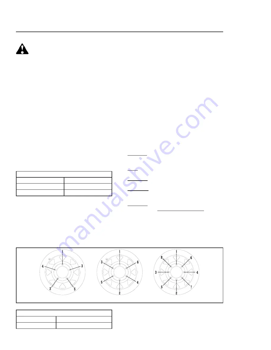
in Diagram 1.

DIAGRAM  1

WHEEL  HARDWARE

SIZE

FOOT-POUNDS

1/2-20 (UNF)

75 FT.-LBS.

9/16-18 (UNF)

110 FT.-LBS.

WHEEL  TORQUE  CHART  &  TIRE  SPECIFICATIONS

Nut/Bolt Location:

1/2-20 (UNF)

Single Wheels

9/16-18 (UNF)

Single Wheels

5  BOLT

6  BOLT

8  BOLT

Summary of Contents for Unverferth 2750

Page 1: ...PART NO 27260 OPERATOR S MANUAL PARTS CATALOG Serial Number D53050100 through D55600099 SEED RUNNER UNITS MODELS 2750 3750 BULK SEED HANDLING PRODUCT U n v e r f e r t h...

Page 2: ...your implement REMEMBER THINK SAFETY A CAREFUL OPERATOR IS THE BEST INSURANCE AGAINST AN ACCIDENT OM 00229 A No accident prevention program can be successful without the wholehearted cooperation of t...

Page 3: ...ne full year from time of consumer delivery Your local dealer will gladly assist you with any war ranty questions The serial number plate is located on the frame as shown in Fig 1 Product Serial Numbe...

Page 4: ...10 ELECTRONIC SCALE 1 11 BASIC OPERATION 1 11 DETAILED PROCEDURE 1 11 DOWNLOADER MODULE OPT 1 14 OPTIONAL AUTO SHUTDOWN FEATURE FOR UM 2510 SCALE ONLY 1 15 OPTIONAL LIGHT KIT 1 15 SECTION II SERVICE L...

Page 5: ...NENTS 4 8 HOPPER COMPONENTS FOR 6 CONVEYOR TUBE 4 10 FOR 8 CONVEYOR TUBE 4 12 IDLER END COMPONENTS FOR 6 CONVEYOR TUBE 4 14 FOR 8 CONVEYOR TUBE 4 16 DISCHARGE SPOUT COMPONENTS FOR 6 CONVEYOR TUBE 4 18...

Page 6: ...full measure of their responsibility It is true that the designer the manufacturer and the safety engineer can help and they will help but their combined efforts can be wiped out by a single careless...

Page 7: ...95445 Part No 97961 Part No 98350 Part No 901580 Part No 95839 Part No 98229 Part No 97048 Part No 97961 Part No 95445 Part No 95839 Part No 235161 Part No 95445 Part No TA1 906109 0 Part No 97575 Pa...

Page 8: ...operating Following Safety Instructions Avoid working under the unit however if it becomes absolutely unavoidable make sure the implement is safely blocked Always make certain everyone and everything...

Page 9: ...severe nausea fainting or death Do not operate engine in closed or confined area Explosive fuel can cause fires and severe burns Stop engine before filling fuel tank Hot parts can cause severe burns D...

Page 10: ...oute hoses and lines carefully to prevent premature failure due to kinking and rubbing against other parts Make sure that all clamps guards and shields are installed correctly Do not relieve hydraulic...

Page 11: ...mpairing devices such as radio headphones etc Keep a first aid kit and properly rated fire extinguisher nearby Keep emergency numbers for fire rescue and poison control personnel near the phone Prepar...

Page 12: ...12 NOTES March 2013...

Page 13: ...ight will vary greatly based on the height of the hitch and the variation in terrain that the Seed Runner is being pulled across Towing vehicle hitch ball or pintle hook must be heavy enough to carry...

Page 14: ...ALWAYS USE TRANSPORT CHAINS WHEN TRANSPORTING IMPLE MENTS FAILURE TO USE CHAINS COULD CAUSE PERSONAL INJURY OR DAMAGE IF IMPLEMENTS BECOME DISENGAGED Transport chains should have a minimum rating equa...

Page 15: ...h lighting and conspicuity marking requirements The center of gravity on the seed tender box is higher than a typical undercarriage Use extreme caution when making turns and enter ing exiting fields C...

Page 16: ...RY CAN CAUSE FIRES AND SE VERE ACID BURNS CHARGE BATTERY ONLY IN A WELL VENTILATED AREA KEEP SOURCES OF IGNITION AWAY WARNING HYDRAULIC SYSTEM MUST BE PURGED OF AIR BEFORE OPERATING TO PREVENT SERIOUS...

Page 17: ...curing it 1 1 8 Wrench Mark position of 1 500 psi setting for reference Decrease Pressure Increase Pressure 5 16 Allen Wrench c Remove the relief adjustment cover by using two wrenches 1 1 8 and a 1 d...

Page 18: ...ng the track IMPORTANT Use caution when parking on in clines Conveyor may pivot on its own as soon as latch is released Pivot Latch Valve Control Lever Transport Latch Klik Pin Conveyor height is adju...

Page 19: ...onveyor be emptied once planter is filled Do this by closing door s on seed tender box shortly before last planter box is full and let conveyor empty out Control Rod NOTE When using the 8 conveyor to...

Page 20: ...sen the two knobs on the side of the deflector pivot deflector up and tighten knobs to hold deflector in place Position conveyor so that the discharge end is located over the seed tender box and the h...

Page 21: ...veyor round and around Doing so will twist hydraulic hoses at pivot point resulting in damage to hoses and potential hydraulic failure IMPORTANT Conveyor must always be latched in cradle except when s...

Page 22: ...Always use both hands with feet on a solid sur face while operating the tarp TARP 5 Do not exert extreme force to roll tarp open or closed If tarp is covered with grain or snow it must be removed bef...

Page 23: ...ically fully empty the Seed Runner and rebalance the scale EZ2000V DETAILED PROCEDURES TURN ON THE SCALE 1 Press ON A brief message is displayed such as HELLO The scale enters GROSS weighing mode Pres...

Page 24: ...will place it in the GROSS mode If the TARE function has not been previously performed the unit will stay in the GROSS mode and the message FOR NET MODE PRESS TARE will scroll across the display The...

Page 25: ...ibration 4 If the correct SETUP number is displayed press the ON key to advance to the CAL number NOTE Factory CAL number is 32640 A Press the SELECT key to cause the flashing digit to count upward B...

Page 26: ...tion 3 Connect DDL to Indicator Connect DDL to Serial Printer port J904 on Digi Star indicator which is located on bottom panel Press the Print Key When indicator printing is completed remove DDL 3a D...

Page 27: ...amount again press the conveyor control button once turning the con veyor off Press the button again turning the conveyor on This cycle can be repeated as many times as necessary NOTE If the conveyor...

Page 28: ...Operation 1 16 NOTES...

Page 29: ...s are acceptable DO NOT use Automatic Transmission Fluid DO NOT mix different oils when topping off the tank Check motor oil level in engine daily See En gine operator s manual for details on oil leve...

Page 30: ...after cylinder rods stop moving Check that cylinders have fully extended or retracted E Check for hydraulic leaks using cardboard or wood Tighten connections according to directions in Torque Chart F...

Page 31: ...duce belt life Too little tension on the belt could result in belt slipping on drive pulley Replace the bottom cover panel and continue to check belt tracking before re tightening the four bolts on ea...

Page 32: ...pening bottom inspection door on conveyor Belt should be in the center of the pulley Operate conveyor at slow speed and tighten or loosen adjustment bolt until belt is running in the center of the pul...

Page 33: ...m NOTE Do not get grease or oil on the brake linings drums or magnets MAGNETS Your electric brakes are equipped with high qual ity electromagnets that are designed to provide the proper input force an...

Page 34: ...d by inserting the ammeter in the line at the magnet you want to check Disconnect one of the magnet lead wire connectors and attach the ammeter between the two wires Make sure that the wires are prope...

Page 35: ...iameter is as follows The machined inner surface of the brake drum that contacts the brake magnet is called the armature surface If the armature surface is scored or worn unevenly it should be refaced...

Page 36: ...Follow steps below to change hydraulic fluid WARNING RELIEVE HYDRAULIC SYSTEM OF ALL PRESSURE BEFORE ADJUSTING OR SERVICING SEE RELIEVING HYDRAULIC PRESSURE IN SERVICE SECTION OF THIS MANUAL WARNING...

Page 37: ...k NOTE When topping off hydraulic fluid tank always use the same fluid as what is already in the tank DO NOT mix different brands or types of hydraulic fluid 7 With the spark plug removed the pump mus...

Page 38: ...69 Florida 800 935 0200 Indiana 800 426 4068 Pennsylvania 800 869 6787 Tennessee 800 946 9412 Ohio 800 840 7295 All tire pressures in psi WHEEL TORQUE REQUIREMENTS CAUTION IMPROPERLY TORQUED WHEEL NUT...

Page 39: ...urn nut 1 3 turn to apply proper torque SAE STRAIGHT THREAD O RING SEAL 1 Insure jam nut and washer are backed up to the back side of smooth portion of elbow adapter 2 Lubricate O Ring VERY IMPORTANT...

Page 40: ...is clear CONVEYOR RUNS TOO SLOW Engine running too slow Increase engine speed Pump not producing minimum required flow and pressure Check pump flow and pressure and correct Pump is worn Repair or repl...

Page 41: ...to proper level B Oil is cold B Run engine at low idle until hydraulic fluid warms C Intake strainer is plugged C Drain reservoir and clean strainer D Return line filter is plugged D Remove and replac...

Page 42: ...2 14 Service MASTER DISCONNECT SWITCH ELECTRICAL SCHEMATIC...

Page 43: ...2 15 Service FRONT TRAILER ELECTRICAL SCHEMATIC Looking Into Tow Vehicle Receptacle Connect to Electric Breakaway...

Page 44: ...2 16 Service TRAILER LIGHTING BRAKE ELECTRICAL SCHEMATIC...

Page 45: ...2 17 Service SEED TANK LIGHTING ELECTRICAL SCHEMATIC...

Page 46: ...2 18 Service NOTES...

Page 47: ...SURE HOIST IS SAFETY RATED FOR AT LEAST 1 000 LBS FAILURE TO DO SO WILL CAUSE DAMAGE TO MACHINE AND MAY CAUSE PERSONAL INJURY WARNING DO NOT WORK UNDER MACHINE AT ANY TIME WHILE BEING HOIST ED INADVER...

Page 48: ...r box using one large forklift with minimum 10 000 lb lift capacity or two 5000 lb capacity forklifts Position single forklift forks through box and secure using four individual chains Wrap each chain...

Page 49: ...00 washers 9405 088 and locknuts 9800 Attach lower part of ladder to extension ladder 3 Slightly loosen bolts connecting extension lad der to undercarriage and lower extension lad der Retighten bolts...

Page 50: ...pivot arm so center pivot tube is aligned with end of pivot arm Carefully lower into position Secure in place using collar 22409TS 3 8x3 1 2 bolt 9390 065 and 3 8 lock nut 9928 Grease pivot point IMPO...

Page 51: ...3 5 Assembly HYDRAULIC DIAGRAM STANDARD HYDRAULICS OPTIONAL HYDRAULICS ELECTRONIC CONTROL VALVE PACKAGE 22660 Refer to Optional Electronic Control Valve assembly instructions in this section OM25004B...

Page 52: ...undercar riage using the four 5 8x1 3 4 bolts 9390 123 and lock nuts 9801 Repeat this process for all four corners of the box Route weigh bar cables along inside edge of box and fasten using the cable...

Page 53: ...around frame securing with cable ties Route weigh bar cables along inside edge of box and fasten using the cable ties 91217 Be certain cables will not get pinched or worn Assemble scale enclosure 279...

Page 54: ...ol route the wiring harness 27938 to the hydraulic control valve Locate the connector with the purple wire Disconnect the connector with the purple wire from the solenoid and connect it to the mating...

Page 55: ...nd secure the entire length of the wiring harness with the included cable ties Be sure to secure the wiring harness near the engine 4 On 6 conveyors only attach baffle 27924 onto the end of the hopper...

Page 56: ...1 1 2 BOLTS THROUGH TOP BARS AS SHOWN THREADED SLEEVE POSITION TOP BAR WELDMENTS BEHIND CLEATSAS SHOWN USE INNER HOLES FOR 6 8 BELTS REF PART NO QTY DESCRIPTION TA4 114400 0 1 BELT INSTALLATION TOOL 1...

Page 57: ...LACINGS TOGETHER BY TURNING THREADED RODS FOR ILLUSTRATION ONLY CONVEYOR SECTION FLOOR STRETCHER ASSEMBLY RIDES ON BOTTOM OF CONVEYOR SECTION FLANGES AND IS HELD IN LINE BY BOLTS CONVEYOR SECTION FLO...

Page 58: ...HAT THE CONVEYOR AND THE SEED RUNNER ARE SECURELY BLOCKED TO PREVENT MOVEMENT THIS WILL PROVIDE A SAFE WORKING ENVIRON MENT WHILE INSTALLING THE ELECTRONIC CONTROL WARNING BEFORE DISCONNECTING HYDRAUL...

Page 59: ...nd turn on electrical and hydraulic power supplies The conveyor will function when the ON button is pressed To stop the conveyor press OFF button on switch IMPORTANT When electrical power supplied is...

Page 60: ...YOR 1 Lower the conveyor to approximately 4 5 feet off the ground 2 Remove the standard spout from the con veyor 3 Slip the optional telescopic spout with T bolt clamp ring 98060 over the conveyor tub...

Page 61: ...using hardware included with light 26789 See figure 3 REMOVE LOWER BRACKET FIG 1 3 Attach light mount bracket 26791B to the bracket weldment using the hardware previ ously removed in Step 2 See figur...

Page 62: ...igure 8 9 Connecting wire harness depends on the Model of your Seed Runner see below A If Seed Runner is equipped with a master key switch connect wire harness to a power lead from the switch Wind up...

Page 63: ...remote use pigtale 21902 included in kit and connect to wire harness Connect opposite end of pigtale to battery NOTE Ring terminal mounts for battery not included See figure 11 10 Position light as n...

Page 64: ...3 18 Assembly NOTES...

Page 65: ...4 1 Parts SECTION IV PARTS...

Page 66: ...4 2 Parts OM04430 BOX DECALS 14 14 15...

Page 67: ...ecal Danger Flammable 1 5 97603 Decal Danger Never Play In On Grain 1 6 97961 Decal Warning Read Understand 1 7 95445 Decal Warning High Pressure Leaks 1 8 97048 Decal Warning Pinch Point 2 9 901854 D...

Page 68: ...4 4 Parts LADDER COMPONENTS OM 04435...

Page 69: ...1 4 901292 CAPPLUG 2 5 9390 100 CAPSCREW 1 2 13UNC x 1 1 4 G5 2 6 9405 088 FLAT WASHER 1 2 USS 2 7 9800 LOCKNUT 1 2 13UNC G5 2 8 9390 058 CAPSCREW 3 8 16UNC x 1 3 4 G5 2 9 9928 LOCKNUT 3 8 16UNC G5 4...

Page 70: ...4 6 Parts DOOR WINDOW PIVOT COMPONENTS OM04431 Revised 082310 1 February 2013...

Page 71: ...2 11 24003TS DOOR WELDMENT LH 1 TAN SPECKLE 12 24004TS DOOR WELDMENT RH 1 TAN SPECKLE 13 9388 025 CARRIAGE BOLT 5 16 18UNC x 1 13 GRADE 5 14 9390 055 CAPSCREW 3 8 16UNC x 1 3 GRADE 5 15 9405 078 FLAT...

Page 72: ...TES 1 22018 Bushing 3 8 Dia 2 2 22409B Collar 1 long 1 Black 3 23939TS Pivot Weldment 1 Tan speckle 4 23951 Bushing 1 3 4 Dia 2 5 23970TS Pivot Weldment for 6 tube 1 Tan speckle 6 24027TS Angle 1 Tan...

Page 73: ...1 4 4 34 9404 021 Lock Washer 3 8 2 35 9405 076 Flat Washer 3 8 USS 3 36 95445 Decal Warning high pressure leaks 2 37 95839 Decal Warning pinch point 2 38 98229 Decal Warning falling or lowering equip...

Page 74: ...4 10 Parts HOPPER COMPONENTS FOR 6 TUBE CONVEYOR OM04428 February 2013...

Page 75: ...N BRUSH 1 19 24620TS STRAP 3 4 x 17 1 2 2 TAN SPECKLE 20 24646TS PLATE 3 1 4 x 11 3 4 2 TAN SPECKLE 21 24986 POLY STRIP 2 1 2 x 5 1 2 5 22 91257 HEX NUT LRG FLG 5 16 18UNC 12 GRADE 5 23 24943TS STAND...

Page 76: ...s HOPPER COMPONENTS FOR 8 TUBE CONVEYOR 7 36 42 15 19 33 20 32 6 45 37 42 23 34 11 43 44 1 28 13 4 8 25 18 30 28 27 14 5 39 40 16 17 26 28 22 21 3 24 12 31 42 29 35 2 21 46 28 9 29 41 38 35 2 February...

Page 77: ...901046 Plastic Knob 1 23 901287 8 Conveyor Belt 1 TA4 100659 0 Belt Splice Kit 9500087 Belt Splice Pin 24 901471 Vinyl Hopper 1 25 901814 Nylon Brush 1 26 902635 Decal Important Baffle 1 27 91256 Fla...

Page 78: ...4 14 Parts IDLER END COMPONENTS FOR 6 TUBE CONVEYOR OM04427 26 February 2013...

Page 79: ...04 019 LOCK WASHER 5 16 16 11 9500310 IDLER COVER 3 TAN SPECKLE 12 9394 006 HEX NUT 3 8 16UNC 10 GRADE 5 13 24756 POLY STRIP 3 X 14 5 32 2 14 97420 FLANGE SCREW 1 4 20UNC X 3 4 14 GRADE 5 15 97189 HEX...

Page 80: ...4 16 Parts IDLER END COMPONENTS FOR 8 TUBE CONVEYOR February 2013...

Page 81: ...A R 11 901287 CONVEYOR BELT 1 TA4 100659 0 SPLICE REPAIR KIT 9500087 BELT SPLICE PIN 12 93415 90 ZERK 2 13 97420 FLANGE SCREW 1 4 20UNC x 3 4 8 GRADE 5 14 9388 024 CARRIAGE BOLT 5 16 18UNC x 3 4 8 GR...

Page 82: ...4 18 Parts DISCHARGE SPOUT COMPONENTS FOR 6 TUBE CONVEYOR OM04426 Revised 082310 1...

Page 83: ...23918TS TOP SHIELD COVER 1 TAN SPECKLE 24 91256 SCREW LR FLG 5 16 18UNC x 3 4 12 GRADE 5 25 22018 BUSHING 3 8 DIA 2 26 9390 003 CAPSCREW 1 4 20UNC x 3 4 5 GRADE 5 27 9405 064 FLAT WASHER 1 4 USS 4 28...

Page 84: ...4 20 Parts DISCHARGE SPOUT COMPONENTS FOR 8 TUBE CONVEYOR OM04539B...

Page 85: ...hreaded 1 GRADE 5 25 93415 90 Zerk 2 26 9388 027 Carriage Bolt 5 16 18UNC x 1 1 2 4 GRADE 5 27 9388 051 Carriage Bolt 3 8 16UNC x 1 8 GRADE 5 28 9390 003 Capscrew 1 4 20UNC x 3 4 2 GRADE 5 29 9390 034...

Page 86: ...4 22 Parts HYDRAULIC COMPONENTS OM 25004A NOTE Valve is shown flipped for clarification Revised 082310 1...

Page 87: ...s Handle with 3 4 16 Ports 1 9 900573 Cylinder 2 1 2 x 5 with Check Valve 3000 PSI 1 99515 Ball Check Valve 99516 Seal Kit 10 900876 Valve Single Spool 15 GPM 4 WAY 3 POSITION 3000 PSI 1 11 25511IV Au...

Page 88: ...VORY WHITE 3 25508IV BATTERY COVER 1 IVORY WHITE 4 25509IV PUMP SHROUD 1 IVORY WHITE 5 25510IV TANK PLATFORM WELDMENT 1 IVORY WHITE 6 25515 PUMP MOTOR MOUNT WELDMENT 1 8 25518 FUEL LINE Hose 1 2 1 9 2...

Page 89: ...CAPSCREW 3 8 16UNC x 1 1 4 4 GRADE 5 35 9394 004 HEX NUT 5 16 18UNC 1 GRADE 5 36 9404 019 LOCK WASHER 5 16 3 37 9404 021 LOCK WASHER 3 8 6 38 9405 070 FLAT WASHER 5 16 USS 2 39 9405 074 FLAT WASHER 3...

Page 90: ...2 45 41 3 58 15 12 13 11 50 35 31 36 50 54 5 7 46 10 7 44 42 19 16 58 21 55 24 57 45 47 22 28 Honda nearest location USA www honda engines com phone 1 800 426 7701 Canada www honda ca phone 1 888 9HO...

Page 91: ...2893 1 Cover Plate Clamp 31 902898 1 Hydraulic Steel Line 1 2 OD 32 902910 1 Suction Strainer w Magnet ITEM PART NO QTY DESCRIPTION 33 902915 1 In Tank Return Filter 9 2GPM A 902123 Cover B 902124 Bow...

Page 92: ...RICAL COMPONENTS ITEM P N DESCRIPTION QTY NOTES 1 902219 LIGHT AMBER LED 2 PRONG 3 2 900956 GROMMET OPEN BACK 9 3 902218 LIGHT RED LED 2 PRONG 6 4 901229 CORD GRIP FITTING 1 5 24936 WIRE HARNESS TANK...

Page 93: ...e Washer 1 2 1 14 9405 088 Flat Washer 1 2 USS 1 15 9390 100 Capscrew 1 2 13UNC x 1 1 4 Grade 5 1 16 9800 Locknut 1 2 13UNC Grade 5 1 17 901811 Decal Power Keyswitch 1 18 902319 Cam Latch 1 19 902321...

Page 94: ...4 30 Parts CABLE RETURN TARP SYSTEM COMPONENTS February 2013...

Page 95: ...uick Release w Hardware 3 14 105829 Tarp Tube Stop 2 15 9003086 Hardware Bag Includes Bolts 2 16 105876 Decal Important Adjusting Rachet 1 17 902065 Cartridge Tube 35 13 Long 1 18 9390 008 Capscrew 1...

Page 96: ...ENT 5000 2 1 4 SQUARE MOUNT 5 9390 123 CAPSCREW 5 8 11UNC x 1 3 4 14 GRADE 5 6 9801 LOCKNUT 5 8 11UNC 30 7 84979 BEND PIN 5 8 DIA 1 8 ELECTRIC BREAKAWAY KIT 1 SEE PAGE 4 37 9 9805 CLEVIS PIN 5 8 DIA x...

Page 97: ...MENT 10 UNDERCARRIAGE 1 TAN SPECKLE 6 97575 DECAL CAUTION TRANSPORT CHAIN 1 7 97961 DECAL WARNING READ UNDERSTAND 1 8 25003 CONSPICUITY MARKING 8 11 RED 7 WHITE 9 98487 GROMMET 1 3 4 DIA 8 10 24687TS...

Page 98: ...4 34 Parts 11 5 12 13 14 1 7 2 10 6 5 19 24 23 18 21 20 22 24 15 13 16 17 8 9 16 17 15 13 5 4 3 UNDERCARRIAGE FENDER COMPONENTS OM04433...

Page 99: ...1 RED 7 WHITE 10 24882TS FENDER LH WELDMENT 3750 1 TAN SPECKLE 11 24883TS FENDER RH WELDMENT 3750 1 TAN SPECKLE 12 9390 108 CAPSCREW 1 2 13UNC x 3 1 4 2 GRADE 5 13 900956 OPEN BACK GROMMET 4 14 902219...

Page 100: ...4 36 Parts AXLE WHEEL COMPONENTS Revised 082310 1...

Page 101: ...67 O D x 1 I D 2 15 97344 Spindle Slotted Jam Nut 1 14UNS 2 Grade 2 16 9391 035 Cotter Pin 5 32 Dia x 1 1 2 2 17 97349 Right Hand Brake Cluster 1 97348 Left Hand Brake Cluster 18 9394 006 Hex Nut 3 8...

Page 102: ...4 38 Parts UNDERCARRIAGE ELECTRICAL COMPONENTS 24896 WIRING HARNESS...

Page 103: ...ull Cord Breakaway Switch ITEM PART NO DESCRIPTION NOTES 25790TS Light Bar Weldment w Decals For Service Only 1 Light Bar Weldment Tan Speckle 2 25045 Wiring Harness 165 Front 3 25046 Wiring Harness 3...

Page 104: ...10 w Sock 2 22578 Telescopic Spout Assembly includes 2 3 5 3 22577 Sock 5 3 8 Dia x8 Long 4 98060 Clamp 5 21759 Flexible Hose 6 Dia x18 Long 6 26290TS Spout Weldment 7 901544 Flex Spout 6 Conveyor 8 C...

Page 105: ...D51320100 Up 10 9390 003 CAPSCREW 1 4 20UNCx3 4 2 GRADE 5 11 901173 WEIGH BAR w 21 CABLE QUICK CONNECT 4 12 9002746 SCALE POWER CORD 20 LONG 1 NOT SHOWN 13 273431 ROLL PRINTER KIT 1 NOT SHOWN 14 9390...

Page 106: ...KIT ITEM PART NO DESCRIPTION QTY 26787 Optional Light Kit 1 1 21902 2 Way Connector 1 2 26789 Light Assembly 1 3 26791B Light Mount Bracket 1 4 26792 Instruction Sheet 1 5 9000106 Cable Tie 6 Long 20...

Page 107: ...dment Tan Speckle 1 12 25061TS Scale Cover Tan Speckle 1 13 22018 Bushing 2 14 9405 064 Flat Washer 1 4 2 15 9390 003 Capscrew 1 4 20UNC x 3 4 4 Grade 5 16 9936 Locknut 1 4 20UNC 4 Grade 5 17 900513 R...

Page 108: ...4 44 Parts OPTIONAL GOOSE NECK HITCH COMPONENTS Front View Rear View February 2013...

Page 109: ...160 Zerk 1 4 28 1 8 91299 185 Capscrew 1 8UNC x 2 1 2 2 Grade 8 9 9390 058 Capscrew 3 8 16UNC x 1 3 4 1 Grade 5 10 9390 101 Capscrew 1 2 13UNC x 1 1 2 4 Grade 5 11 9390 124 Capscrew 5 8 11UNC x 2 16 G...

Page 110: ...Platform for Units Less Undercarriage Includes Items 1 5 1 25746TS Scale Base 2 2 9390 065 Capscrew 3 8 16UNC x 3 1 2 8 3 9390 124 Capscrew 5 8 11UNC x 2 8 4 9801 Locknut 5 8 11UNC 8 5 9928 Locknut 3...

Page 111: ...4 47 Parts NOTES February 2013...

Page 112: ...L MANUALS SEEDTENDER 27260 INDD MARCH 2013 3 JUNE 2014 4 MARCH 2015 4 www unverferth com...

Reviews: