-21-
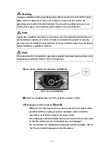
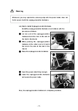
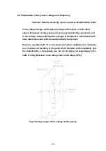
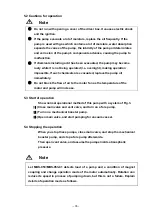
Do not apply more than 150V by setting of the 100V system.
Power supply circuit is damaged when you install wrong power supply voltage
selection connector and in addition of ignition might.
5.6
External control and alarm output
Connector for external control and alarm output is possessed to a motor
driver box. (
Refer
to figure 6)
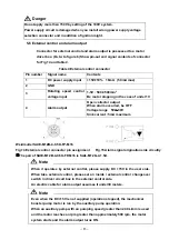
Show pin-out and signal contents of connector
for Fig 14 and table 4.
Table 4 External control connector
Pin number
Signal name
Contents
1
DC power supply input
+15V±10% 18mA (50mA max)
2 GND
3
Rotating speed control
voltage input
1-5V : 500-3500min
-1
Be motor stopping in the case of under 1V
4 Alarm
output
Open collector output
When alarm occurred, be OFF
Voltage range 5V
~
30V
Sink current : 5mA maximum
Weidmuller SAIE-M12B-4-0.5U-FP-M16
Fig.14 External control connector pin assignment
※
The pair of SAIE-M12B-4-0.5U-FP-M16 is SAIL-M12G-4-1.5U.
When it operates by external control, please supply DC +15V in the user side.
When take external control, please set an inside / external control changeover
switch in driver circuit box in the external control side.
An electric cable for alarm output assumes it under30 meters.
Even when the DC+15V is not supplied (operation stopped), the mechanical
booster pump motor is run by the auxiliary pump operation.
When an auxiliary pump with an pumping speed greater than 240 L/min is used
and the motor reaches an rpm greater than approximately 500 rpm, the motor
system starts and the alarm output turns ON.
Fig.15 Alarm signal origination side circuitry
Danger
Note
Note

