background image


32 

ULVAC CRYOGENICS INCORPORATED


13.   Troubleshooting 

When any failure or unusual phenomenon occurs in the equipment, at first perform 

the fault diagnosis shown in the following table.    When contacting us, it is 

requested to check the lighting status of PLC lamp arranged to the electrical circuit 

in advance. 


Problem 

Possible Cause 

Corrective Action 

(1)  Equipment fails to 

start by pressing the 
RUN/STOP switch. 
(The RUN/STOP 
switch does not light) 

The main power source 
(breaker) is turned OFF. 
 

Turn ON the main power 
source. 

The power cord is not 
connected. 

Connect the power cord 
correctly. 

The circuit breaker is turned 
OFF. 
 

Turn ON the circuit breaker. 

The fuse is blown. 

Replace fuse with new one. 
If the fuse is blown 
repeatedly, please contact 
us. 

The emergency stop button is 
pressed. 

Reset the emergency stop 
switch by turning it to the 
right, and restart. 

(2)  Equipment fails to 

start even if the 
RUN/STOP switch 
lights up. 


LN

2

 level is not decreased to 

the re-starting level. 

When LN

2

 level is decreased 

to 75% or less, the 
production starts 
automatically. 

(3)  Power breaker trips. 

Short-circuit or electric 
leakages occur. 

Please contact us. 

(4)  GN2 AL. lights on. 

The RUN/STOP lamp 
flickers at the same 
time. 

GN10i is suspended. 

Check the electric wiring of 
GN-10i, or 
Suspend and resume EMP 
and GN-10i. 

IM-120 is suspended. 
 

Check the dry air supply 
pressure. 

Nitrogen gas supply 
decreases, or the pressure is 
lowered temporarily.   

Refer to “9-5-3. Corrective 
action when GN2 AL. occurs” 
and restart EMP 14A. 


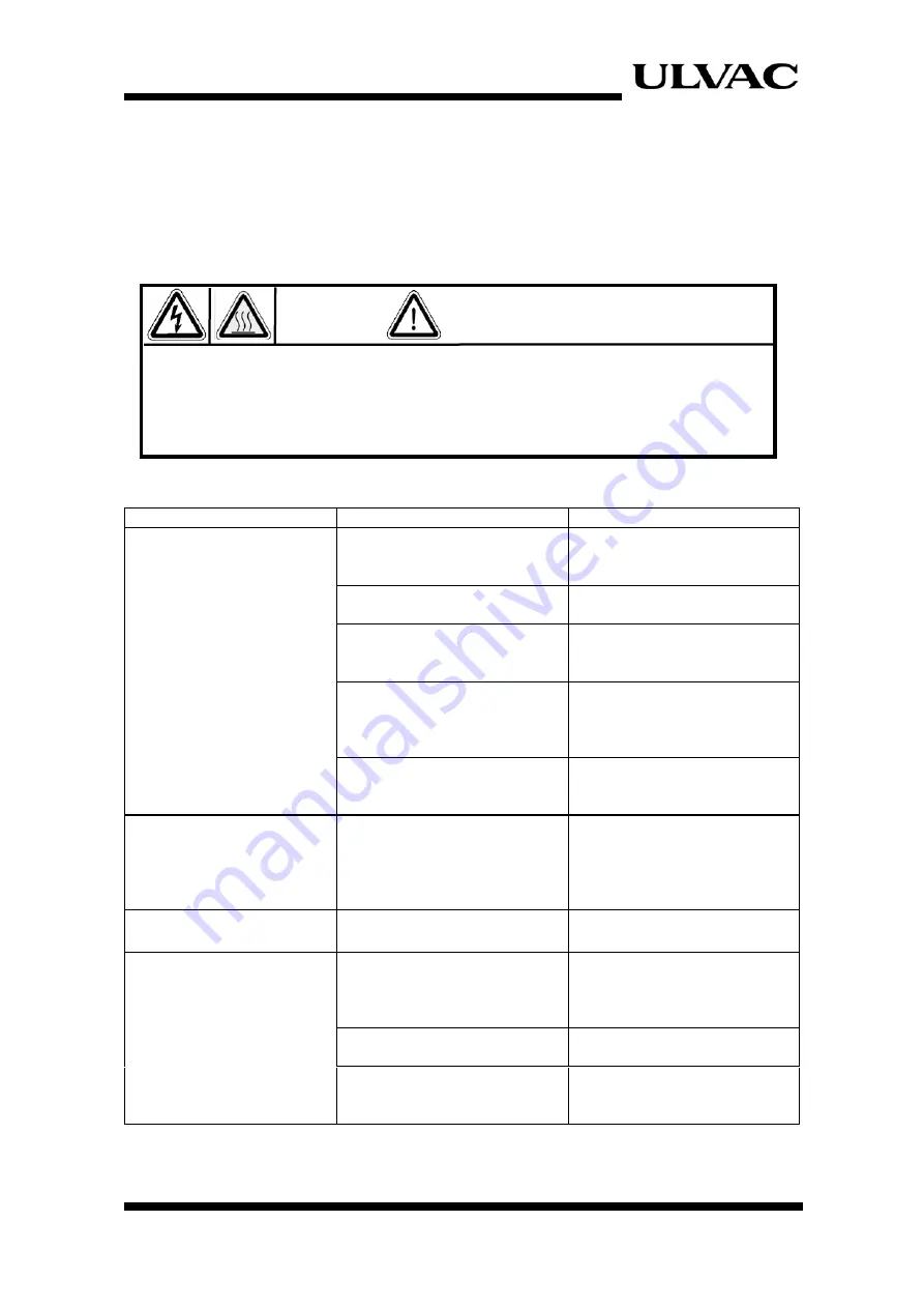
Ensure that main power is disconnected before inspecting the power source or 

inside of the equipment.  Some parts of the equipment may remain in high 

temperature right after stopping operation.    Use caution to avoid burn injury. 

WARNING 

Summary of Contents for EMP-14A

Page 1: ...al sensors the cryocooler falls under row 6 A 2 d 2 of the control list established by The Wassenaar Arrangement which is equal to row 10 2 of appended table 1 of Japan s Export Trade Control Order Cu...

Page 2: ......

Page 3: ...close at hand so that you can use for reference during operation If you purchased our other products and or optional devices with this product read relevant instruction manuals carefully 1 It is stri...

Page 4: ...caution describes safety hazards or unsafe practices which could result in personal injury or equipment damage Toxic gas or chemicals used There is a risk of severe injury upon contact Corrosive chemi...

Page 5: ...of EMP 14A front door and lower panel Figure 2 3 11 2 4 Inside the lower panel on the back 11 2 5 EMP 14A Electrical circuit Figure 2 4 12 2 6 EMP 14A Top side Figure 2 5 12 3 Flow Diagram 13 4 Specif...

Page 6: ...lly 26 9 1 Connecting liquid nitrogen flexible hose 26 9 2 Dispense liquid nitrogen 26 9 3 Disconnecting flexible hoses 27 10 Automatic Transfer of Liquid Nitrogen 28 10 1 Inspections before starting...

Page 7: ...he oxygen concentration of 18 or below is defined as an oxygen depleted state Choose a well ventilated and good air circulated location to install the present unit and install a ventilator with a capa...

Page 8: ...of burns if it is touched directly Carry out maintenance repair etc at least 30 minutes after the unit is stopped In this unit high pressure Helium gas is filled To disassemble or dispose of the unit...

Page 9: ...s regulations or guidelines when disposing of our products We provide Safety Data Sheet SDS of our products upon your request Please contact us when necessary WARNING When the refrigerator unit may ha...

Page 10: ...4 ULVAC CRYOGENICS INCORPORATED This page intentionally left blank...

Page 11: ...his equipment please refer to the operation manual for SA115 C 1 3 PSA Pressure Swing Adsorption Nitrogen Generator type GN 10i PSA Nitrogen Generator GN 10i generates highly concentrated nitrogen fro...

Page 12: ...D 2 Component Description Figure 2 1 Front view of EMP 14A Figure 2 2 Operation panel of EMP 14A Emergency Off Button Operation Panel Pressure Gauge LN2 Manual Dispense Port SA115 C Display Air Entran...

Page 13: ...the port may reach extremely low temperature use cautions not to touch such port during or right after dispensing liquid nitrogen Pressure gauge Displays the pressure inside the dewar SA115 C display...

Page 14: ...ispense port To be referred to as Manual supply The manual supply is terminated automatically in 10 minutes This button lights green during manual supply and blinks from 30 seconds before the automati...

Page 15: ...OGENICS INCORPORATED 9 Maintenance This light illuminates when the maintenance interval of GN 10i is approaching Temperature meter Temperature meter is an optional It displays the temperature inside t...

Page 16: ...and lower panel Figure 2 4 Electrical circuit Figure 2 5 Top of EMP 14A Level sensor converter Fuse Circuit breaker PLC Terminal block Automatic transfer port Pressure gauge Liquid nitrogen dewar Cold...

Page 17: ...t for charging helium gas Do not touch except when needed as touching it may result in helium leakage OPERATION switch Use this lever to switch between start and stop of SA115 C Normally move the leve...

Page 18: ...ignal from each sensor In the event of an error please inform the status of input and output lights of the sequencer when contacting us Level sensor converter An electric component for detecting the a...

Page 19: ...ol Circuit Temperature Indicator TI Optional Pressure Meter Pressure Relief Valve Flexible Hose LN2 Dispense Ambient Temperature Solenoid Valve Pressure Control Valve Coldhead Cable Helium Gas Tube He...

Page 20: ...han LN2 manual dispense port EMP 14A is for indoor use only As EMP 14A is air cooled make sure that the air intake and exhaust ports are always open not blocked 4 2 PSA Pressure Swing Adsorption nitro...

Page 21: ...0i Voltage 100VAC 10 single phase Power capacity 15A or more Power consumption Approx 400W 50 60 Hz Connection 3 prong plug 5 3 Dry air for IM 120 when using IM 120 Pressure 0 5MPa 1 0MPa Flow rate 12...

Page 22: ...lities should be located nearby 2 The ambient temperature should be from 10 C to 35 C and humidity is 80 or below 3 Keep the following spaces for maintenance Spaces other than the back are required on...

Page 23: ...dry air supply Connect the other side of the tube to AIR IN connector on the back side of IM 120 6 4 Utility connection of EMP 14A Remove the back panel of EMP 14A and locate holes for utility connec...

Page 24: ...ircuit breaker and supply electricity by turning on the breaker in the electric circuit part of EMP 14A Be sure to confirm that the power is supplied to the sequencers or other parts in the electric c...

Page 25: ...site side of nitrogen gas tube to the nitrogen gas supply valve on the generator 6 4 3 Connection of Nitrogen gas generator remote cable Connect a remote cable to the remote connector located inside o...

Page 26: ...A B 0 5SQ P24V 011 0 5SQ 1 2 SV1 SV2 R2 Name Symbol Earth Leakage Breaker Terminal Cover Noise Filter Power Supply Programmable Controller Capacitance Level Meter Converter Level Indicator Temperature...

Page 27: ...M Display N2 GAS ALARM COMP Startup signal Reserve Cryogenic Manual Electromagnetic Valve Cryogenic Auto Electromagnetic Valve Room Temperature Electromagnetic Valve Cooling Water Electromagnetic Valv...

Page 28: ...en it starts operation normally the POWER switch on EMP 14A flashes with long term light on and short term light off Note Once operation starts RUN STOP switch does not work for the next six minutes I...

Page 29: ...it reaches to 100 8 3 Shutdown When EMP 14A is turned OFF with the RUN STOP button the RUN STOP light flashes with shorter illumination and longer off for 10 seconds and all the operations stop includ...

Page 30: ...when the amount of liquid nitrogen inside is 75 or more production may not be resumed at the time of rebooting This is the common precaution when rebooting 8 5 2 Corrective action for COMP AL 1 Check...

Page 31: ...0 2MPa and flow rate is 10NL min turn ON the EMP 14A RUN STOP switch to restart 8 6 Emergency off In case of an emergency press the emergency off button on the front panel to disconnect the control po...

Page 32: ...oduction of liquid nitrogen stops during manual supply operation When nitrogen gas supply is suspended liquid nitrogen cannot be dispensed When the EMP 14A is in standby for automatic transfer when th...

Page 33: ...re to connecting Push down the outer ring of the EMP 14A side joint and pull out the flexible hose CAUTION When disconnecting flexible hoses make sure that they return to room temperature Note that di...

Page 34: ...ic transfer will also be terminated when the RUN STOP or AUTO READY of EMP14A are turned OFF the LN2 level of EMP 14A is 0 or supply of nitrogen gas stops Liquid nitrogen cannot be dispensed manually...

Page 35: ...es Manual dispense is not available during eco mode To dispense manually reset eco mode and wait for 6 minutes until the nitrogen gas generator resumes operation When the liquid nitrogen level is lowe...

Page 36: ...urs or 2 years Shorter 20 000 hours 3 Coldhead 1 Oil adsorber Helium pipe joint GN 10i Air Compressor GN 10i Filter 2 GN 10i Solenoid valve Parts 1year 2years 5years IM 120 Membrane IM 120 Prefilter I...

Page 37: ...mer inspection The EMP 14A is a high pressure manufacturing equipment Please follow the applicable laws or regulations when operating and maintaining this equipment Be sure to turn off the main power...

Page 38: ...op button is pressed Reset the emergency stop switch by turning it to the right and restart 2 Equipment fails to start even if the RUN STOP switch lights up LN2 level is not decreased to the re starti...

Page 39: ...um gas to the appropriate pressure Contact us for more information on charging 6 RUN STOP switch blinks and EMP does not start LN2 production Alarm light is not lit RUN STOP switch is pressed less tha...

Page 40: ...the helium gas lines and refrigerator cables properly The level sensor fails to detect correctly Please contact us 9 The rate of Liquid Nitrogen production declines Cold head and oil adsorber exceed...

Page 41: ...on blinks Only 30 seconds left until the time limit of 10 minutes of manual dispense Press MANU START button again to continue dispending manually 12 AUTO READY button and AUTO SUPPLY button blink alt...

Page 42: ...Gas Tube 1 3m Single Head Wrench 1 Glass Fuse 3 3A x 2 2A x 1 Instruction Manual 1 This book GN 10i Remote Cable for Nitrogen Generator 1 5m Instruction Manual 1 IM 120 Remote Cable for Nitrogen Gene...

Page 43: ...nts and on site visits for the following seven conditions In those cases the cost shall be your own expense even though the product is within the warranty period 1 Breakdowns due to improper storage o...

Page 44: ...ed to your company or your customers by failures of ULVAC CRYOGENICS products and compensation for damages to products other than ULVAC CRYOGENICS products and other services are not covered under war...

Page 45: ...Chigasaki Kanagawa 253 0085 Japan Sales Tel 81 467 85 8884 Service Engineering Division Tel 81 467 85 9366 Fax 81 467 83 4838 ULVAC CRYOGENICS KOREA INC www ulvac cryo co kr 107 Hyeongoksandan ro Che...

Page 46: ...CS 2 ULVAC CRYOGENICS INCORPORATED This page intentionally left blank...

Page 47: ...2019OR04 First edition The model of PSA nitrogen gas generator has been changed The format for Warnings and Cautions has been changed Disposal Considerations has been added 15 Warranty Company addres...

Page 48: ...R 2 ULVAC CRYOGENICS INCORPORATED This page intentionally left blank...

Reviews: