background image

Page 7

Getting around the Interface

A full discussion of how to operate your device is covered in the 

section titled “Operation” on page 44. We recommend that you 

review this information in it’s entirety. Contained in this section is 

a only a brief overview to the topic.

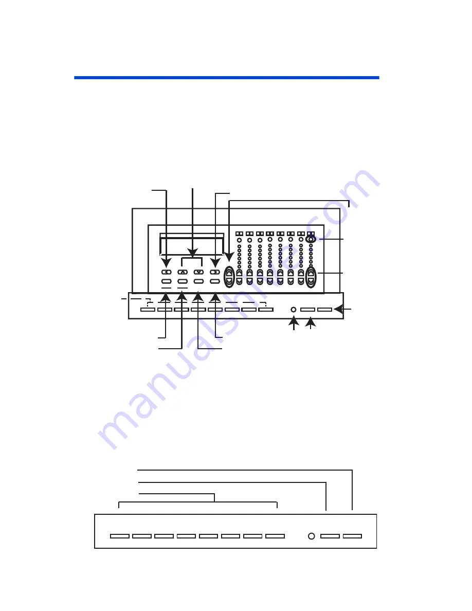
Figure 15 - D4200 Buttons

Controls

With the cover closed, you can access the first eight 

SCENE


buttons and the 

MAX

 and 

OFF

 buttons. 

1 9

2 10

3 11

4 12

5 13

6 14

15

16

M

aster

M

aster

P

age

P

age

Z

ones

Z

ones

C

lear

C

lear

M

enu

M

enu

C

ancel

C

ancel

S

elect

S

elect

S

ave

S

ave

2-Line, 16-Character LCD

IR Receiver

Scene  

Programming or

 Recall

Master
Dim/Bright

All Off

Zone
Dim/Bright

7

8

Zone
Information 
Display

All Zones to  
Maximum Brightness

Change Zone

Clear

Select Option and Save

Menu and  

Cancel Button

Previous Field or

Change Scene Blank

Shortcut

Previous/Next

Menu Option

Next Field or
Change Scene Bank
Shortcut

2

4

5

6

7

8

1

3

9

0

MAX.

OFF

Off Button

Max Button

Scene Button

Summary of Contents for D4006

Page 1: ...4000 Series Control System Topics at a Glance Installation See Installation Guide Quick Start Configuration 10 User Interface 7 Initial Setup 18 Scheduling 62 Scene Recording 53 Detailed Operation 44...

Page 2: ...etup 18 Accessing the Configuration Menus 19 Network Settings 20 The Patch 23 Zone to Channel Patch 24 Dimmer to Circuit Patch 27 Configuring Dimmers 28 Devices with Dimmers Only D4006 33 Miscellaneou...

Page 3: ...ess for a minimum or 100 hours before dimming is permitted 5 For best results lamp brands and types should not be intermixed on a circuit 6 Disconnect power when servicing the dimmer fixture or when c...

Page 4: ...n information Accompanying this guide should be an installation guide covering all the connections and other requirements of proper installation Common Topics How to operate the device see page 44 Pow...

Page 5: ...ly wire size run length load requirements Consider any regularly scheduled events 2 Follow the installation instructions covering physical installation connections and wring of your device 3 Use the i...

Page 6: ...and the MAX and OFF buttons 1 9 2 10 3 11 4 12 5 13 6 14 15 16 Master Master Page Page Zones Zones Clear Clear Menu Menu Cancel Cancel Select Select Save Save 2 Line 16 Character LCD IR Receiver Scen...

Page 7: ...the Zone identification and status buttons the Zone level indicators and the programming navigation buttons Navigating Menus To navigate the menus use the programming navigation buttons Figure 11 Pro...

Page 8: ...es to Zones 25 32 are active Breakfast P1 S01 TUE 04 29p LE Page Number P1 Zones 1 8 Days of week Scene Indicates Schedule is active P2 Zones 9 16 Scene Name Indicates Station is Locked P3 Zones 17 24...

Page 9: ...ch model has a slightly different feature set so the application of each step may vary slightly Table 1 Find your Product 4104 or 4106 4200 Quick Start on page 11 Part numbers D4104 D4106 Control Chan...

Page 10: ...review Setting the Network ID on page 20 Step 7 For load types that are not incandescent adjust dimmer load types appropriate See Configuring Dimmers on page 28 Step 8 If there is more than one maste...

Page 11: ...e Configure the Clock on page 52 Step 13 If scheduling events around sunrise or sunset setup the astronomical time clock on page 53 Step 14 Record your scenes see Recording a Scene on page 53 Step 15...

Page 12: ...ork ID see page 33 Step 5 Set the starting channel number see page 33 Step 6 For any load types which are not incandescent adjust dimmer load types as appropriate See Configuration of Dimmers at anoth...

Page 13: ...vigating the Menus on page 49 Step 5 Power up unit Step 6 Perform Power Up Initialization on page 16 or review Setting the Network ID on page 20 Step 7 Perform setup of other network devices dimmers e...

Page 14: ...nts on page 62 Step 15 Celebrate You re all done Depending upon the desired specific behavior of this device configuration may be complete or additional modifications may be necessary Regardless a ful...

Page 15: ...rk The ID for every device on the network must be unique Enter a unique ID number for this station in the space provided this space When you ve finished entering the network ID press the down arrow to...

Page 16: ...t This completes the initial power up configuration However before your unit is completely ready to go please return to Quick Start Configuration p 10 or turn a few more pages p 18 to continue the set...

Page 17: ...lity of the basic operation menus can be found in the section Operation on page 44 The advanced menus required for setup are accessed the same way as the operation mode menus by pressing the Menu key...

Page 18: ...able To enter advanced mode follow the procedure below Step 1 Push the MENU button until the display reads the current day and time Step 2 Push and Hold the MENU button for approximately 10 seconds un...

Page 19: ...assigned to it Network ID which is not set or which is set to Zero 0 will not participate on the network Valid Range 1 127 unique network ID These numbers may have been assigned at the factory prior t...

Page 20: ...This helps when identifying this device from other network devices The network name may be up to 8 characters long Remoting to another Master Station LCD stations can be used as a remote to another LC...

Page 21: ...Series Architectural Lighting Controller Page 22 OPERATION SETUP QUICK START OVERVIEW CONFIGURATION Although the LCD messages displayed on a remote are the same as the master the configuration menus o...

Page 22: ...used with the Network Channel which is discussed below Network Channel The slot on the network to which level information is placed by a zone Dimmer relays and other devices which directly control loa...

Page 23: ...evices like dimmers relays etc The Zone Channel patch establishes the relationship between the zones and the network channel There are two ways to set the patch one which assigns a channel to each zon...

Page 24: ...press SELECT Your zones then will be renumbered To Assign Zones non consecutively or edit a particular zone s settings Step 1 From the advanced menus see page 19 find the menu which reads then press S...

Page 25: ...wing each occupied by a different tenant and as such the particular circuiting for every wing changing periodically You could setup the system so that all dimmers relays and controllers had to be rec...

Page 26: ...atching The default patch for zones is a consecutive patch starting at zone 1 channel 1 The default patch for dimmers is a consecutive patch starting at dimmer 1 network channel 1 Zones and dimmers ne...

Page 27: ...tion Menus on page 19 Although there are many items which may be configured two are critical Network Channel Number Dimmer Type All other parameters are related to the behavior of the dimmer as part o...

Page 28: ...number or rather 1 6 In some situations when you have multiple master stations you will need each one set to a unique set of network channels Valid ranges are 1 2048 Dimmer Type The most critical conf...

Page 29: ...ed then the lights will shut off If the event is cancelled then the lights will remain in their current state for a time period then the process will repeat Blink option to cancel off or override on T...

Page 30: ...ill respond to a level or readback request from the network The default setting is Yes If you have a situation where more than one dimmer relay or other device is assigned to the same network channel...

Page 31: ...ced menus see page 19 find the menu which reads then press SELECT Step 2 Using Up or Down scroll through the names of the other panels connected to the network until the one you want to configure is v...

Page 32: ...age 24 For more information about the implication of the two settings please reference the indicated sections and page numbers To set the network ID on a device with only dimmers Step 1 The display sh...

Page 33: ...d hold the up button for approximately 3 seconds The display then will be steady Step 2 Use the Up Down arrows until the desired starting channel number is shown Step 3 Push and hold the Down Set butt...

Page 34: ...gs on this menu can be changed using the following process OFF S18 THU 08 48P MENU MISC SETTINGS MISC SETTINGS READBACK REQ ON MISC SETTINGS BUMP MODE MAX MISC SETTINGS BACKLIGHT DIMMED MISC SETTINGS...

Page 35: ...ossible that the actual state of the circuit will differ from that of this master station In this case it s helpful for this device to periodically check the state of each circuit This is called readb...

Page 36: ...master time clock is ignored and only the local settings are used RECV Receive Only device will listen to broadcasts from a master time clock and set local time to the master time clock but will never...

Page 37: ...al Services IR Port The IR port can either be enabled or disabled by this setting Valid values are as follows Enabled The IR port will receive and process IR signals Disabled The IR port will ignore a...

Page 38: ...goes inactive When the user interface is locked no operation or configuration changes may be made The valid settings for this property are Enabled The user interface should be locked when the input i...

Page 39: ...ts in which case the cycle repeats 6 35pm If the event has not been overridden the off event will be activated Max Zones This setting is used to set the maximum number of zones this device will addres...

Page 40: ...Page 41 Remote To ID numbers unless already at zero 0 Assign Zones Exclusions Zones Zone Labels...

Page 41: ...r the entry station Step 2 If already installed remove the entry station from the wall and unplug the network cable Step 3 Set the Network ID dipswitch to the Network ID of the master station to which...

Page 42: ...Page 43...

Page 43: ...e Control of the lighting look recall of scenes and changes to configuration are possible With the cover closed you can access the first eight SCENE buttons and the MAX and OFF buttons Figure 14 Scene...

Page 44: ...ng levels for example keeping a minimum light level for safety reasons With the cover open you can also access the LCD display the Master Up and Down buttons the individual Zone Up and Down buttons th...

Page 45: ...evels You can control the lighting levels in two ways You can change all the lights at once or change individual lighting levels without changing the presets The approximate lighting level for each Zo...

Page 46: ...vels Open the cover to access the lighting level buttons Using the Zone Up and Down buttons adjust the individual lighting levels for each of the zones The approximate lighting level for each Zone is...

Page 47: ...vel indicators Figure 18 Zone Status Buttons To check a Zone Step 1 Press a Zone status button The LCD display shows the Zone number or name if you have programmed one the precise lighting level is di...

Page 48: ...ner as indicated above The maximum range for the remote control is approximately 30 feet line of sight Additional infrared receivers are also available Navigating the Menus To navigate the configurati...

Page 49: ...function globally enables or disables the sequencer To enable or disable the sequencer Step 1 Press the Menu Cancel button Step 2 Press the Up and Down buttons until SEQUENCER flashes on the LCD disp...

Page 50: ...Page 51...

Page 51: ...setting AstroTime Set the Date Time Using Up Down Left Right set the current time date and 12 or 24 Hour mode Set Daylight Savings Time Use Up Down to select Off No daylight savings time North America...

Page 52: ...SETUP ASTROTIME SETUP ASTROTIME LATTITUDE 00N SETUP ASTROTIME SURISE 00 00 SETUP ASTROTIME SUNSET 00 00 SETUP ASTROTIME WEEK XX SETUP ASTROTIME MIDNIGHT 12 00 SETUP ASTROTIME SR 06 04 SS 17 56 Settin...

Page 53: ...the Up and Down buttons beneath the LCD display to pick the Scene you wish to record Step 5 Press the Select Save button to record the lighting levels and fade time The LCD display shows RECORDING SC...

Page 54: ...s 1 16 When the Double Bump feature is on tapping the MAX or OFF buttons twice overrides any high and low limits Therefore if MAX and OFF are set at any levels other than full bright and full off the...

Page 55: ...elect Save button to save the value and edit the label Step 8 Select another Zone or Scene to edit or press the Menu Cancel button twice to exit this menu Excluding Zones From a Scene Your device allo...

Page 56: ...ude a zone When you press a Zone Up button the corresponding changes to a digit which represents the least significant digit of the affected zone s ID Example Zone 16 is represented by 6 25 is represe...

Page 57: ...Lock Code when recording Scenes and editing any data Setting the Station Lock also sets the Record Lock When you turn the Station Lock OFF The Record Lock stays ON Setting the Record Lock Code The Re...

Page 58: ...000 and 999 as the Preset Scene buttons 1 to 8 and MAX 9 and OFF 0 can be used to enter the code directly To set the station lock code Step 1 Press the Menu Cancel button Step 2 Press the Up and Down...

Page 59: ...s the Select Save button to save the value RECORD LOCK flashes again Step 6 Press the Menu Cancel button to exit this menu Enabling the Station Lock Be sure to set the Station Lock Code before enablin...

Page 60: ...numbering from zero 0 Shortcut Use a code number between 000 and 999 as the Preset Scene buttons 1 to 8 and MAX 9 and OFF 0 can be used to enter the code directly Step 2 Press the Select Save button...

Page 61: ...schedule Step 1 Press the Menu Cancel button Step 2 Press the Up and Down buttons until EDIT SCHEDULE flashes on the LCD display Step 3 Press the Select Save button The current Event number flashes S...

Page 62: ...position for each of the 7 days of the week Day of week listed i e M for Monday indicates that the event will occur on that day Day of week absent i e for Monday indicates that the event will not occ...

Page 63: ...SCHEDULER flashes on the LCD display Step 3 Press the Select Save button The current status of the scheduler flashes Step 4 Press the Up and Down buttons to change the value Step 5 Press the Select S...

Page 64: ...ent number flashes The sequence Events are displayed in the following format STOP indicates the end of the sequence and the sequencer is disabled after a STOP Event is executed LOOP indicates the sequ...

Page 65: ...lude some other scene or control command then put it back at a later time Enabling the Sequencer The sequence can be started and stopped either from the operational level menus Enabling the Sequencer...

Page 66: ...disabled after a STOP Event is executed LOOP indicates the sequencer will immediately restart the sequence and will run continuously Events after a START or LOOP command are not executed Step 4 Press...

Page 67: ...Layout Charts The tables and charts in this section are designed to help you with the layout and configuration of your system They are very helpful when conceptualizing how all components will interac...

Page 68: ...Page 69 Table A1 Zone Labels and Network Channels Form Zone Zone Label Network Channel or group 1 2 3 4 5 6 7 8 9 10 11 12 13 14 15 16 17 18 19 20 21 22 23 24 25 26 27 28 29 30 31 32...

Page 69: ..._ BW ____ Dimmer 3 Type Standard MarkX Tu Wire Non Dim Network Channel ________ Groups A _________ B _________ C _________ D _________ Max _________ Min ________ Cutoff _________ BW ____ Dimmer 4 Type...

Page 70: ...Page 71 Table A3 Scene Labels and excludes Scene Scene Label Excluded Zones 1 2 3 4 5 6 7 8 9 10 11 12 13 14 15 16...

Page 71: ...er Page 72 OPERATION SETUP QUICK START OVERVIEW CONFIGURATION Table A4 Scheduled Events Actions can be Scene Max Off Seq on Seq Off Resume Cell On Event Time Days of Week SMTWTFS Action Blink Warn Y o...

Page 72: ...up Actions can be Scene Max Off Skip Loop Stop or Goto Step Seq Step Action Delay Seq Step Action Delay 1 17 2 18 3 19 4 20 5 21 6 22 7 23 8 24 9 25 10 26 11 27 12 28 13 29 14 30 15 31 16 32 Up to 64...

Page 73: ...1 N 88 W Montgomery AP 32 N 86 W Selma Craig AFB 02 N 88 W Talladega 33 N 86 W Tuscaloosa AP 33 N 88 W ALASKA Anchorage AP 61 N 150 W Barrow S 71 N 157 W Fairbanks AP S 65 N 148 W Juneau AP 58 N 135 W...

Page 74: ...AFB 38 N 122 W Fresno AP S 37 N 120 W Hamilton AFB 38 N 122 W Laguna Beach 34 N 118 W Livermore 38 N 122 W Lompoc Vandenberg AFB 35 N 121 W Long Beach AP 34 N 118 W Los Angeles AP S 34 N 118 W Los An...

Page 75: ...34 N 118 W Santa Paula 34 N 119 W Santa Rosa 39 N 123 W Stockton AP 38 N 121 W Ukiah 39 N 123 W Visalia 36 N 119 W Yreka 42 N 123 W Yuba City 39 N 122 W COLORADO Alamosa AP 37 N 106 W Boulder 40 N 105...

Page 76: ...S 26 N 80 W Miami Beach Co 26 N 80 W Ocala 29 N 82 W Orlando AP 29 N 81 W Panama City Tyndall AFB 30 N 86 W Pensacola Co 30 N 87 W St Augustine 30 N 81 W St Petersburg 28 N 83 W Stanford 29 N 81 W Sa...

Page 77: ...in Home AFB 43 N 116 W Pocatello AP 43 N 113 W Twin Falls AP S 42 N 114 W ILLINOIS Aurora 42 N 88 W Belleville Scott AFB 39 N 90 W Bloomington 40 N 89 W Carbondale 38 N 89 W Champaign Urbana 40 N 88 W...

Page 78: ...som AFB 41 N 86 W Richmond AP 40 N 85 W Shelbyville 40 N 86 W South Bend AP 42 N 86 W Terre Haute AP 39 N 87 W Valparaiso 42 N 87 W Vincennes 39 N 88 W IOWA Ames S 42 N 94 W Burlington AP 41 N 91 W Ce...

Page 79: ...wling Green AP 36 N 86 W Corbin AP 37 N 84 W Covington AP 39 N 85 W Hopkinsville Ft Campbell 37 N 88 W Lexington AP S 38 N 85 W Louisville AP 38 N 86 W Madisonville 37 N 87 W Owensboro 38 N 87 W Paduc...

Page 80: ...ngfield Westover AFB 42 N 73 W Taunton 42 N 71 W Worcester AP 42 N 72 W MICHIGAN Adrian 42 N 84 W Alpena AP 45 N 83 W Battle Creek AP 42 N 85 W Benton Harbor AP 42 N 86 W Detroit 42 N 83 W Escanaba 46...

Page 81: ...N 89 W Clarksdale 34 N 91 W Columbus AFB 33 N 88 W Greenville AFB 34 N 91 W Greenwood 33 N 90 W Hattiesburg 31 N 89 W Jackson AP 32 N 90 W Laurel 31 N 89 W Mccomb AP 32 N 90 W Meridian AP 32 N 89 W Na...

Page 82: ...dron AP 43 N 103 W Columbus 41 N 97 W Fremont 41 N 96 W Grand Island AP 41 N 98 W Hastings 41 N 98 W Kearney 41 N 99 W Lincoln Co S 41 N 97 W McCook 40 N 101 W Norfolk 42 N 97 W North Platte AP S 41 N...

Page 83: ...3 N 106 W Albuquerque AP S 35 N 107 W Artesia 33 N 104 W Carlsbad AP 32 N 104 W Clovis AP 34 N 103 W Farmington AP 37 N 108 W Gallup 36 N 109 W Grants 35 N 108 W Hobbs AP 33 N 103 W Las Cruces 32 N 10...

Page 84: ...43 N 76 W Utica 43 N 75 W Watertown 44 N 76 W NORTH CAROLINA Asheville AP 35 N 83 W Charlotte AP 35 N 81 W Durham 36 N 79 W Elizabeth City AP 36 N 76 W Fayetteville Pope AFB 35 N 79 W Goldsboro Seymo...

Page 85: ...ont 41 N 83 W Hamilton 39 N 85 W Lancaster 40 N 83 W Lima 41 N 84 W Mansfield AP 41 N 83 W Marion 41 N 83 W Middletown 40 N 84 W Newark 40 N 82 W Norwalk 41 N 83 W Portsmouth 39 N 83 W Sandusky Co 41...

Page 86: ...123 W The Dalles 46 N 121 W PENNSYLVANIA Allentown AP 41 N 75 W Altoona Co 40 N 78 W Butler 41 N 80 W Chambersburg 40 N 78 W Erie AP 42 N 80 W Harrisburg AP 40 N 77 W Johnstown 40 N 79 W Lancaster 40...

Page 87: ...Lat Long SOUTH DAKOTA Aberdeen AP 45 N 98 W Brookings 44 N 97 W Huron AP 44 N 98 W Mitchell 44 N 98 W Pierre AP 44 N 100 W Rapid City AP S 44 N 103 W Sioux Falls AP 44 N 97 W Watertown AP 45 N 97 W Ya...

Page 88: ...on Co 30 N 95 W Huntsville 31 N 96 W Killeen Robert Gray AAF 31 N 98 W Lamesa 33 N 102 W Laredo AFB 28 N 99 W Longview 32 N 95 W Lubbock AP 34 N 102 W Lufkin AP 31 N 95 W McAllen 26 N 98 W Midland AP...

Page 89: ...risonburg 38 N 79 W Lynchburg AP 37 N 79 W State City Lat Long Norfolk AP 37 N 76 W Petersburg 37 N 78 W Richmond AP 37 N 77 W Roanoke AP 37 N 80 W Staunton 38 N 79 W Winchester 39 N 78 W WASHINGTON A...

Page 90: ...re AP 45 N 91 W Fond Du Lac 44 N 88 W Green Bay AP 44 N 88 W La Crosse AP 44 N 91 W Madison AP S 43 N 89 W Manitowoc 44 N 87 W State City Lat Long Marinette 45 N 88 W Milwaukee AP 43 N 88 W Racine 43...

Page 91: ...uring the warranty period but agrees only to repair or replace defective equipment returned to its plant in Tualatin Oregon This Warranty is void on any product that has been improperly installed over...

Page 92: ......

Page 93: ...5600 Tech Line 1 800 959 6004 Leviton Manufacturing Co Inc 59 25 Little Neck Parkway Little Neck NY 11362 2591 Telephone 1 800 323 8920 FAX 1 800 832 9538 Visit Leviton s Web site at http lms leviton...

Reviews: