14
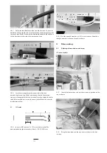
4.3.7
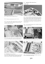
Guide the identified loose tubes into the flex tube. This can be
facilitated by keeping the end of the loose tubes bundled together with
a piece of tape. Make a loop with the flexible tube behind the shelf and
fix the flex tube into the clip of the termination plate.
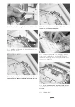
4.3.8
Attach the strength member connector to the back
termination plate using a Philips screwdriver. Avoid unnecessary
crossing of strength member and loose buffer tubes. Attach the cable
with the releasable tie wraps on the outer jacket. Mount the cover on
the flex tube holder.
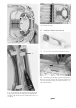
B
IFC cable
4.3.9
In case of IFC: remove X = 700 mm of outer jacket. The
recommended length of secondary fiber L = 1250-1500 mm.
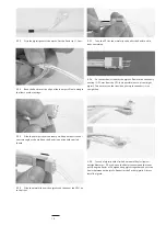
l
4.3.10 Cut the strength member at l = 60 mm maximum. Attach the
strength member fixation and install as shown.
5
Fiber routing
5.1
Splicing of loose tube on the tray
12 splice module
5.1.1
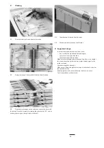
Identify the loose tubes and put the tie wraps in position on the
tray as shown.
5.1.2
Bring the loose tubes on the tray and mark them at the first
tie-wrap.


