Section 5: Configuration of the frequency converter
Table 5.1. The
possible configuration variants of remote start
Value of
par. 2.08
Function
Description
0
DI1 = START / STOP
DI2 = DIRECTION
Applying voltage to digital input 1 results in start
and voltage removal – in stopping the system.
The state of digital input 2 determines the change
of the direction of the electric motor rotation.
1
DI1 = START
RIGHT
DI2 = START LEFT
Applying voltage to digital input 1 will start the
electric motor. Applying voltage to digital input 2
causes the motor to start in the opposite
direction.
2
DI1 =
PULSE START
DI2 =
PULSE STOP
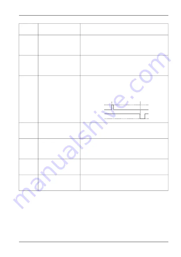
The frequency converter will start after a pulse is
fed to the DI1 input at a high DI2 state.
The direction of rotation depends only on a sign
of a referencing-unit.
STOP
START
DI1
DI2
3
DI1 =
PULSE START
DI2 =
PULSE STOP
DI3 = DIRECTION
as above, additionally the DI3 digital input is
responsible for changing the direction
4
DI1 = START / STOP
Applying voltage to digital input 1 results in start
and voltage removal – in stopping the system.
The direction of rotation depends only on a sign
of a referencing-unit.
5
DI1 or DI2
= START / STOP
Applying voltage to the DI1 or DI2 digital inputs
(according to the "or" logic gate) will cause the
system to start.
6
DI1 and DI2
= START / STOP
Applying voltage to the DI1 and DI2 digital inputs
(according to the "and" logic gate) will cause the
system to start.
TWERD Power Electronics
27


