background image

AB Connectors Limited 

Specification No. 528 

ABCIRP Connector Series 

Assembly and wiring Instructions 

AB Connectors Limited                                                     Issue 9: July 2010


Page 37 of 41 


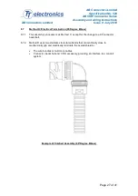
Appendix E: Steel Band Termination Assembly Process 


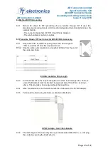
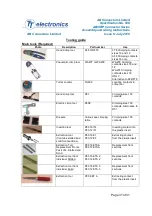
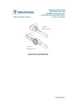
Hand Banding Tool -AB Part No. -ABB600058  

Prepare the band in the following manner: IMPORTANT: Due to the connector  / adaptor 

circumference, it may be necessary to prepare the band around the cable retention area. 

Roll band through the buckle slot twice

Pull on band until mark (>|) is within approximately 6.4mm of the buckle slot. the band may be 

tightened further if desired. 

Note: prepared band should have mark (>|) visible where approximately shown. 


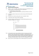
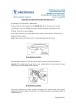
Hand Banding Tool Step 1  

Squeeze gripper release lever and insert band into the front end of the opening of the tool.  

Important:  The  straight  leg  of  looped  band  is  to  be  installed  with  the  circular  portion  of  looped 
band facing downward towards the black handle.  


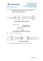
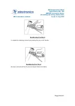
Hand Banding Tool Step 2  

Aligning  the  band  and  the  tool  with  the  shield  termination  area,  squeeze  black,  pull-up  handle 
repeatedly until it locks against the tool body. (This indicates the band is compressed to the pre-
calibrated tension). 

Summary of Contents for AB Connectors ABCIRP Series

Page 1: ...ed Specification No 528 ABCIRP Connector Series Assembly and wiring Instructions AB Connectors Limited Issue 9 July 2010 Page 1 of 41 ABCIRP Series Circular Multi pin Electrical Connectors Assembly and Wiring Instructions ...

Page 2: ...rientation 10 4 2 Alignment Pin 11 5 Individual Wire Termination 12 5 2 Individual Wire Termination Crimping Cables 13 5 3 Individual Wire Termination Contact insertion Method 1 14 5 4 Individual Wire Termination Contact insertion Method 2 16 6 Contact Extraction 17 7 Screen termination system 19 7 2 Method A Termination Procedure For In line Wire Bundles 20 7 3 Procedure for a Fixed Connector wit...

Page 3: ...ly 2010 Page 3 of 41 Appendices Appendix A Tooling data 28 Appendix B Dimensional positions of contacts in fixed free shells 33 Appendix C Guidance for the use of 90 backshells 34 Appendix C Steel Band Termination Assembly Process 35 Appendix D Backshell Torque Values 37 Appendix E Trouble Shooting 39 Appendix F Contact addresses 41 ...

Page 4: ...shell cam tracks and secondly by positive lock indicators in the form of An audible click when fully mated Alignment of coloured dots when fully mated 1 1 5 ABCIRP connectors are available in 7 sizes from shell size 18 to shell size 40 with arrangements having 7 to 60 contacts 1 1 6 Crimp contacts are available in sizes 16 12 and 8 AWG 1 1 7 Insulator angular orientation is available for occasions...

Page 5: ...ry the ABCIRP modular bayonet coupling connector offers several advantages to the user Metal clip retained removable crimp contacts Positive lock location of contacts Circlip retained removable insulator allowing for angular re positioning Rapid coupling and uncoupling 120 rotation of th e coupling nut Vibration resistant loosening of the coupling nut under vibration or shock condition is prevente...

Page 6: ...stic Low fire hazard Grommet Rubber Low fire hazard Contacts Copper Alloy Retaining Clip Beryllium Copper Accessory Aluminium Alloy 1 2 2 Plating Finishes Shell Zinc Cobalt Black Passivation Contacts Gold or Silver Accessory Zinc Cobalt Black Passivation 1 2 3 Environmental Ratings Shock 75g Vibration 5 to 500Hz long endurance 30 hour test at 10g Acceleration 50g Mechanical Endurance 500 mating cy...

Page 7: ...rt to reverse gender 2 1 3 Insert Pin or Socket Removable orientatable retains the contacts and can be used in either fixed or free shells 2 1 4 Circlip Retains the insert in the shell 2 1 5 Contacts Pin or Socket Crimped to the conductors 2 1 6 Retaining clip Retains the contacts in the insert 2 1 7 Grommet Resilient rubber seal for the individual wire terminations It has a special cut out featur...

Page 8: ...ns at the top of the ramps ensure positive locking and long service life 2 2 2 Insert Pin or Socket Removable orientatable retains the contacts and can be used in either fixed or free shells 2 2 3 Circlip Retains the insert in the shell 2 2 4 Contacts Pin or Socket Crimped to the conductors 2 2 5 Retaining clip Retains the contacts in the insert 2 2 6 Grommet Resilient rubber seal for the individu...

Page 9: ... with those of the accessory 3 1 3 The spinning knurled locking nut prevents grommet twist when tightening 3 1 4 Accessories are available to take heat shrink boots screening systems and conduit Angled versions are also available to guide cable routing Please consult the catalogue or ask the sales desk for more information on the type available Hint When engaging the accessory onto the connector l...

Page 10: ... seen on either the front face or the location keyway 4 1 3 Before the circlip is used it is best practice to bend the circlip through 90 so that a spring washer effect is formed in the circlip This will not only aid the assembly process but will take up any linear movement of the insulator within the shell 4 1 4 Align the insulator orientation letter required with the key in the shell and press i...

Page 11: ...he size and complexity of the arrangement 4 2 2 Note The additional polarising device is inserted into the pin insulator only 4 2 3 It is recommended that at least two of these pins be installed per connector These alignment pins should not be removed once installed Example of two 40 A35 Contact arrangements with X and Y orientations mated together 25 out of the 35 available contacts can misalign ...

Page 12: ... AB Crimp Contact Part Number Dimension L mm Strip Length Pin Socket 16 22 ABCIRP1622KPK ABCIRP1622KLK 5 6mm 16 20 ABCIRP1620KPK ABCIRP1620KLK 5 6mm 16 ABCIRP16KPK ABCIRP16KLK 5 6mm 16 14 ABCIRP1614KPK ABCIRP1614KLK 5 6mm 12 40 ABCIRP1240KPKP80 ABCIRP1240KLKP80 7 8mm 12 20 ABCIRP1220KPKP80 ABCIRP1220KLKP80 7 8mm 12 16 ABCIRP1216KPKP80 ABCIRP1216KLKP80 7 8mm 12 ABCIRP12KPKP80 ABCIRP12KLKP80 7 8mm 1...

Page 13: ...ripped conductor into the contact crimp bucket Ensure conductor is fully pushed in and that insulation is tight to crimp bucket 1 2 5 Check inspection hole to see if the conductor strands are visible If they are not visible check the conductor strip length and check for foreign objects in the crimp bucket 1 2 6 Operate the empty crimp tool once to ensure the crimping dies are completely open and t...

Page 14: ...ons as supplied by manufacture 5 3 2 Locate the correct hole for the appropriate wire Load the contact into the insert by hand Note It is best practice to work from one side only inserting from left to right or top to bottom in an orderly fashion Some arrangements have a radial pattern where working from the centre and working outwards is best Randomly inserting contacts is more likely to result i...

Page 15: ...n Hint If you push forward on the back face of the grommet it should not buckle If it does then the grommet has not been tucked into position correctly This can cause the grommet to tare when the backshell is assembled and could affect sealing 5 3 8 To ensure that the correct wire number has been inserted into the correct hole check that the lettering and step in the grommet align correctly 5 3 9 ...

Page 16: ... the rear of the insulator ensuring that the recess on the grommet aligns with the corresponding raised section on the insert 5 4 6 Tuck the grommet in between the connector shell and the insert until the shoulder on the grommet is pushed almost level with the top of the serrations on the shell A simple tool is available to help when tucking the grommet into position Hint If you push forward on th...

Page 17: ... all wires 5 4 11 Checking the dimensions shown in Appendix B will verify that the contact is seated correctly As an extra final visual check all contacts should be around the same height with no visible differences in height from insert face 5 4 12 Assemble the rear backshells and accessories following steps 5 4 8 to 5 4 11 2 Contact Extraction 2 1 1 The extraction tool can be utilised for both t...

Page 18: ... allow the contacts to be repositioned into a different hole Important Note To prevent damage to the grommet when pushing the contact through the grommet hole use the Grommet extraction tool 2 1 7 Simply place the contact fully into the tool into the tool Using the tool push the contact through the grommet until the end of the tool in visible at the other end Remove the contact from the tool 2 1 8...

Page 19: ... the connector backshell and the interwoven knitted mesh at the opposite end Typical Braided Sock Connector Shell Size Part Number Length Diameter Up to shell size 32 ABBMBS035015 150mm 35mm Shell sizes 36 40 ABBMBS05015 150mm 50mm Braided Sock Lengths Note Make certain the sock is expanded to the correct diameter before cutting to length To aide this operation the use of an inner storage tube of ...

Page 20: ...A 8 3 1 Cut the braid sock to the required length and remove inner storage tube Fold one end of the Braidsock back inside itself by approximately 15 to 20mm as shown right This provides a clean edge without sharp sections 8 3 2 Slide sock over threaded portion of RFI Adaptor 8 3 3 Terminate braid sock to the RFI adaptor using a securing band shown in Appendix C Termination of Braid Sock To RFI Ada...

Page 21: ...e previous page 8 3 8 Secure the knitted mesh with an appropriate tinned copper wire 8 3 9 Slide braid sock RFI adaptor assembly forward over grommet and screw the adaptor on to the connector Take care to ensure correct seating of the grommet Tighten to recommended torque see Appendix D 8 3 10 Using a suitable shell holding fixture gently draw the braid down the wire bundle to its full length and ...

Page 22: ...ns AB Connectors Limited Issue 9 July 2010 Page 22 of 41 8 3 11 Dress the whole assembly Check the securing band for correct assembly 8 3 12 Appropriate tape can be applied to protect ends of braid sock if required This will cover the braid if it has not been folded in on itself Method A Completed ...

Page 23: ...ation exposing the screen for a length of 100mm and trim off all of this exposed screen 8 5 2 Strip the cable outer insulation to a length of 200mm from the end of the cable as shown ECHSA Insulation Strip Length 8 5 3 Cut the braid sock to the required length and remove inner storage tube Fold one end of the Braidsock back inside itself by approximately 15 to 20mm as shown above This provides a c...

Page 24: ...en for a length of 170mm 8 6 4 Cut back the screen leaving a length of 100 125mm 8 6 5 Crimp the contacts on load the connector and assemble the grommet as per the instructions on pages 7 to 11 inclusive Braid Sock Assembly 8 6 6 Cut the braid sock to the required length and remove inner storage tube Slide the braid sock over knurled section of the inner component of CRA accessory and terminate us...

Page 25: ...to the cable in the following order SCHSA backshell Ensure the O ring seals are seated correctly CRA accessory braid sock assembly CRA accessory locking nut conduit adaptor Installation of CRA and SCHSA Accessories Section showing O ring and Braided Sock Position 8 6 9 Secure Knitmesh as detailed in method A Pre Knitmesh Assembly 8 6 10 The later stages of the assembly are as per that detailed in ...

Page 26: ...ctor Series Assembly and wiring Instructions AB Connectors Limited Issue 9 July 2010 Page 26 of 41 Assembled Knitmesh 8 6 11 Pull the conduit system forward over braid sock termination and secure to rear threads of the RFI conduit adaptor Completed Assembly ...

Page 27: ...8 7 1 This assembly procedure is as Method C except for the change to a 90 0 connector backshell 8 7 2 Method D uses two stainless steel clamp bands that concentrically close to mechanically grip and electrically terminate the overall shield to The wire bundles or multi core cables Connector backshell and CRA accessory providing an interface to a conduit system Example of finished Assembly 90 Degr...

Page 28: ...ition Insertion tool Extraction Tool Grommet extraction tool 16 22 Pin ABCIRP1622KPK 0 22 2 AF8 WA27F OR FT8 WA27E TH592 Blue P80 16 ITL P80 16 ET P80 16 GET 0 34 3 16 22 Skt ABCIRP1622KLK 0 22 2 Red 0 34 3 16 20 Pin ABCIRP1620KPK 0 50 0 75 3 Blue 16 20 Skt ABCIRP1620KLK Red 16 18 Pin ABCIRP1618KPK 0 75 0 93 4 Blue 16 18 Skt ABCIRP1618KLK Red 16 Pin ABCIRP16KPK 0 93 1 5 5 Blue 16 Skt ABCIRP16KLK R...

Page 29: ... tool 12 20 Pin ABCIRP1220KPKP80 0 50 0 75 3 FT8 W27E TH592 Yellow P80 12 ITL P80 12 ET N A 12 20 Skt ABCIRP1220KLKP80 12 18 Pin ABCIRP1218KPKP80 0 75 0 93 4 12 18 Skt ABCIRP1218KLKP80 12 16 Pin ABCIRP1216KPKP80 0 93 5 1 5 12 16 Skt ABCIRP1216KLKP80 0 93 5 1 5 12 14 Pin ABCIRP1214KPKP80 1 94 2 08 5 12 14 Skt ABCIRP1214KLKP80 12 Pin ABCIRP12KPKP80 2 50 3 00 7 12 Skt ABCIRP12KLKP80 12 40 Pin ABCIRP1...

Page 30: ...osition Insertion tool Extraction Tool 100 60 Pin ABBP10060KPKP80 6 N A D55E D51 MRP31038 N A N A P80 8 ETA 100 60 Skt ABBP10060KSKP80 100 Pin ABBP100KPKP80 10 MRP0925 100 Skt ABBP100KSKP80 8 40 ABBP8 40KPKP80 4 MRP31042 8 40 ABBP8 40KSKP80 4 8 16 ABBP8 16KPKP80 0 93 1 50 Consult Factory M310 Consult Factory Consult Factory 8 16 ABBP8 16KSKP80 0 93 1 50 8 ABBP8KPKP80 9 N A ERMA19600 22390 N A 8 AB...

Page 31: ...1 Crimping size 100 contacts Electric crimp tool D55E Crimping size 100 contacts Alternative to D51 Die sets Various see crimping table Crimping size 100 contacts Insertion tool P80 16 ITL P80 12 ITL Inserting contact into the plastic insert Extraction tool Contains slotted and solid front sections P80 16 ET P80 12 ET Extracting contact from the plastic insert Extraction Tool Replacement Fronts Pa...

Page 32: ...ontact retention tester HT250 3 Applies a load to the front of the contact to ensure it is seated correctly Contact pin retention test probe 68 016 01 size 16 68 012 01 Size 12 Fits onto contact retention test probe to test socket contacts Contact socket retention test probe 67 016 01 Size 16 67 012 01 Size 12 Fits onto contact retention test probe to test socket contacts Pin Contact alignment gau...

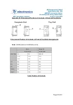
Page 33: ...x B Dimensional Positions of Contacts in fixed and free Shells Dimensional Position of Contacts in Fixed Free Shell Arrangements Note All dimensions in millimetres mm Shell Size Pin A Socket B Contact Size Contact Size 16 12 16 12 1 0 1 0 1 0 1 0 1 0 1 0 18 6 6 3 0 2 6 20 6 6 3 0 2 6 22 6 6 3 0 2 6 28 32 6 6 3 0 2 6 36 40 6 6 3 0 2 6 Table Position of Contacts ...

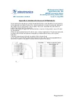
Page 34: ...orten the service life of the connector When routing cables through a 90 bend behind the c onnector It is important to use a 90 outlet for this purpose While it is recommended that a 90 outlet is used i n all such applications This document provides a guide to the minimum bend that can be applied to a cable without the use of the correct backshell The bend radius shown is through the centre of the...

Page 35: ...AB Connectors Limited Specification No 528 ABCIRP Connector Series Assembly and wiring Instructions AB Connectors Limited Issue 9 July 2010 Page 35 of 41 ...

Page 36: ...AB Connectors Limited Specification No 528 ABCIRP Connector Series Assembly and wiring Instructions AB Connectors Limited Issue 9 July 2010 Page 36 of 41 Typical Torque and Strap Wrench ...

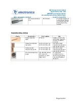
Page 37: ...til mark is within approximately 6 4mm of the buckle slot the band may be tightened further if desired Note prepared band should have mark visible where approximately shown Hand Banding Tool Step 1 Squeeze gripper release lever and insert band into the front end of the opening of the tool Important The straight leg of looped band is to be installed with the circular portion of looped band facing d...

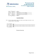
Page 38: ...Assembly and wiring Instructions AB Connectors Limited Issue 9 July 2010 Page 38 of 41 Steel Banding Tool Step 3 Complete the clamping process by squeezing the grey cut off handle Steel Banding Tool Step 4 Remove excess band from the tool and inspect shield termination ...

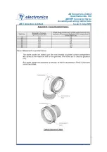
Page 39: ...s on connector faces 2 Dry out the connector check the grommet and retighten the backshell to the specified torque value Water Ingress to Backshell 1 No grommet 2 Incorrect cable for grommet 3 Loose backshell accessory 4 Grommet damaged during contact insertion 5 Grommet not seated correctly 1 Fit Grommet 2 Build up insulator diameter 3 Check for grommet damage 4 Tighten to specified value 5 Resea...

Page 40: ...tion Check coloured identification band 2 Check contacts for signs of damage 3 Check socket contact clips for signs of damage High resistance intermittent or no contact 1 Socket contact clips missing 2 Poor crimp joints 3 Wire broken or damaged 1 Check contact for missing clip 2 Check crimp and crimp tool settings 3 Check wire for signs of damage including very tight bend radii Problem locking the...

Page 41: ...el 01 919 934 5181 Fax 01 919 934 5186 Email mailto abconnectors abautomotiveusa com France 17 Rue du Kefir Senia 418 94567 ORLY Cedex Tel 33 0 1 46 87 38 89 Fax 33 0 1 46 87 40 38 Tooling UK Glenair Miles Roystone 40 Lower Oakham Way Oakham Business Park Mansfield Notts NG18 5BY Tel 01623 638100 Fax 01623 638111 USA Daniels Manufacturing Corp 526 Thorpe Road Orlando FL32824 8133 Tel 01 407 855 61...

Reviews: