AB Connectors Limited
Specification No. 528
ABCIRP Connector Series
Assembly and wiring Instructions
AB Connectors Limited Issue 9: July 2010
Page 17 of 41
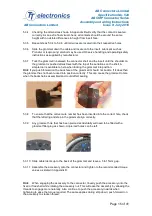
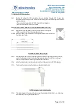
inserting the contact into the insert until it clicks into place. When inserting a socket
contact it is good practice to place a socket guide pin in the front of the contact to
prevent any rubber from the grommet web entering the socket contact.
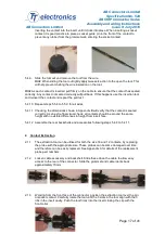
5.4.9
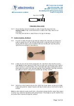
Slide the tool out and remove the tool from the wire.
Hint: When sliding the tool out lightly apply tweezers action to the open the tool. This
will help prevent chafing the wire insulation on the tool.
Hint: As each contact is inserted pull firmly on the cable to ensure that the contact has seated
correctly. Any contact not seated correctly will pull back. If this happens use the insertion tool
and reinsert the contact and repeat the pull test.
5.4.10 Repeat steps 5.5.8 to 5.5.9 for all wires.
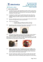
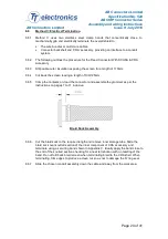
5.4.11 Checking the dimensions shown in Appendix B will verify that the contact is seated
correctly. As an extra final visual check, all contacts should be around the same
height with no visible differences in height from insert face.
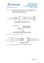
5.4.12 Assemble the rear backshells and accessories following steps 5.4.8 to 5.4.11.
2. Contact Extraction
2.1.1
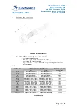
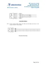
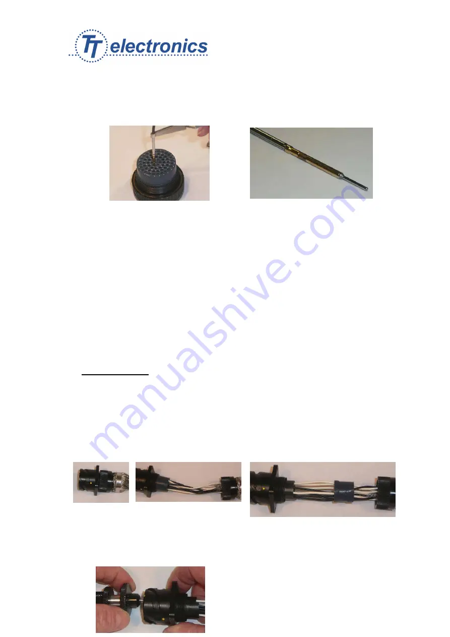
The extraction tool can be utilised for both the size 16 and 12 contacts, by replacing
the probe with the appropriate size. These probes can become damaged over time
and therefore can be easily replaced. See Appendix A for details of the replacement
probe part numbers.
2.1.2
Loosen cable accessory and backshell. Slide these down the cable to allow easy
access to the rear of the connector. Slide the grommet and cable idents back
approximately 70mm.
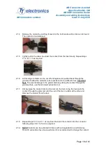
2.1.3
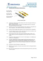
Working from the front face of the connector, position the extraction tool over the pin
or socket contact. Carefully rotate the tool until the 3 slots in the tool align with the 3
ribs in the insert cavity. Push the tool firmly into the insert closing the clip with the
front collar.

