AB Connectors Limited
Specification No. 528
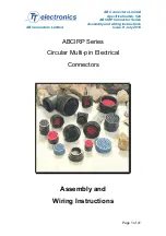
ABCIRP Connector Series
Assembly and wiring Instructions
AB Connectors Limited Issue 9: July 2010
Page 11 of 41
insulator can now be removed and repositioned or replaced as required.
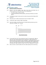
4.2 Alignment Pin
4.2.1
For high density, symmetrical contact arrangements, where very few contacts are
being used, additional devices may be necessary to completely remove the
possibility of cross mating like connectors. These devices take the form of pins,
which occupy key contact positions in the insulator depending on the size and
complexity of the arrangement.
4.2.2
Note. The additional polarising device is inserted into the pin insulator only.
4.2.3
It is recommended that at least two of these pins be installed per connector. These
alignment pins should not be removed once installed.
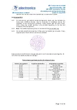
Example of two 40-A35 Contact arrangements with X and Y orientations mated together. 25
out of the 35 available contacts can misalign.
Table showing optimum position for alignment pins.
Contact arrangement
Insulator Orientation
Alignment pin position
18-19
All
Any one hole
20-15
All
Any one apart from G
22-14
All
Hole K & R
24-10
All
Any one hole apart from G
28-21
All
Holes E & e
32-A13
All
Hole 10
36-A22
All
Holes 14 & 17
40-A35
All
Holes 1 & 24
40-A60
N
Hole 3 & 51
W, X, Y & Z
Holes 26 & 59

