background image


         Did you find what you’re looking for? The Truth Hardware Web site is a great resource  
         for the latest product and installation information.  It’s available at www.truth.com 
 

31

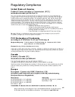
Regulatory


Compliance


United States of America 
Federal Communications Commission (FCC)


Unintentional emitter per FCC Part 15 


Note:  This equipment has been tested and found to comply with the limits for a Class B digital device, 
pursuant to part 15 of the FCC Rules. These limits are designed to provide reasonable protection against 
harmful interference in a residential installation. This equipment generates, uses, and can radiate radio 
frequency energy and, if not installed and used in accordance with the instructions may cause harmful 
interference to radio communications.  However, there is no guarantee that interference will not occur in a 
particular installation.  If this equipment does cause harmful interference to radio or television reception, 
which can be determined by turning the equipment off and on, the user is encouraged to try to correct the 
interference by one or more of the following measures: 


o


Reorient or relocate the receiving antenna. 

o


Increase the separation between the equipment and receiver. 

o


Connect the equipment into an outlet on a circuit different from that to 
which the receiver is connected. 

o


Consult the dealer or an experienced radio/TV technician for help. 

 
Warning: Changes or modifications not expressly approved by Truth Hardware could void the FCC 
compliance and negate your authority to operate the product.


FCC Declaration of Conformity 

According to 47 CFR, Parts 15.107 and 15.109 Class B 


Responsible party:   Truth Hardware, 700 West Bridge St., Owatonna, MN  55060  


www.truth.com  or 1-800-324-4487 


Product: Sentry II Hand Held Remote (43.53) 


This device complies with part 15 of the FCC Rules.  Operation is subject to the following two conditions: (1) 
This device may not cause harmful interference, and (2) this device must accept any interference received 
including interferences that may cause undesired operation.


Canada 
Industry Canada (IC) 

Unintentional emitter per ICES-003 


This class B digital apparatus complies with Canadian ICES-003. 
Cet appareil numérique de la classe B est conforme á la norme NMB-003 du Canada. 


Operation is subject to the following two conditions: (1) this device may not cause interference, and (2) this 
device must accept any interference, including interference that may cause undesired operation of the 
device.


Europe 
European Community EMC Directive (CE)


Compliance with these directives implies conformity to the following 
European Norms or Regulations: 


Emissions


Immunity


ETSI  EN 300-220-1 v1.3.1 (2000-09)    


ETSI  EN 301 489-3 v1.2.1 (2000-08) 

ETSI  EN 300-220-3 v1.1.1 (2000-09) 


EN  55014-2: 1997 

ETSI  EN 301 489-3 v1.2.1 (2000-08) 
EN  55014-1: 1997 

CONFORMS TO ANSI/UL STD 325; CERTIFIED TO CAN/CSA STD C22.2 NO. 68

Summary of Contents for Sentry II

Page 1: ...and Spanish versions available at www truth com technicalsupport HS Skylight Motorization System Installation Instructions Made in USA An FKI Industries Company 700 West Bridge Street Owatonna MN 550...

Page 2: ...MUST be correctly installed and is a required part of the power skylight system It is intended to help prevent injury that could result from reaching into the skylight area during operation The corre...

Page 3: ...installation 8 Screen Interlock 11 Normal operation 14 Battery backup 16 Wall mounted switch panel 17 Rain sensor 17 HPI 19 Status feedback 20 Power blind control 20 General trouble shooting 22 DIP sw...

Page 4: ...e range must be maintained between 140 F 60 C to 5 F 20 C Single motor vs multiple synchronous motor application Most applications of the Sentry II HS system will be a single motor on a single skyligh...

Page 5: ...12473 92 6 Chain 11533 7 Sprocket 30654 8 Terminal block 9 Strain Relief Items 8 thru 9 are part of 10 Screen Interlock hardware kit 12482 11 Rain sensor 12 Screws 4 Size A 12 24 X 5 8 TF Ph FH self t...

Page 6: ...to install the rain sensor each control unit needs a separate rain sensor Consult main wiring diagram for wiring requirements o Power mini blinds The Sentry II control unit is capable of controlling...

Page 7: ...Did you find what you re looking for The Truth Hardware Web site is a great resource for the latest product and installation information It s available at www truth com 7 Main wiring diagram...

Page 8: ...ver 80 lbs or wider than 40 refer to the Synchronous Motor section of the manual 2 Install Chain Base Remove existing manual operator and or chain base if present Install the chain base included with...

Page 9: ...y power must be off until instructed to turn it on Remove high voltage protection cover Install Hit Loc strain relief as shown Route 120 VAC supply wiring through the rear inlet and strain relief on c...

Page 10: ...rive sprocket Once the motor is fully engaged with the chain base the control box is effectively locked into the chain base motor drive assembly Secure with 4 12 24 X 5 8 Ph FH Machine Screws in the l...

Page 11: ...of the screen interlock is the responsibility of the installer Screen interlock installation Install screen interlock to the screen frame as shown below using 6 32 X 3 8 Phillips PH Self Threading Ma...

Page 12: ...ocation and into control board opening Connect low voltage wires to the control panel as outlined for each accessory Accessories and other control options are wired to the motor designated as the Lead...

Page 13: ...r trim button 6 32 X 3 8 Phillips PH Self Threading Machine Screw WARNING Use of a longer screw will damage motor If needed a spare screw is supplied in the hardware pack 10 Power Up and Initializatio...

Page 14: ...tablish its operating parameters which will be stored in permanent memory Once permanent memory is established it is unaffected by loss of power of any duration 11 Program Remote Control If a remote c...

Page 15: ...position Press the opposite function while the motor is running the motor will stop in that position Status Light Indicator During operation the status light located in the skylight motor and on the...

Page 16: ...are primarily used to supply emergency backup for computer equipment Truth Hardware is not a supplier of battery back up systems To determine the proper VA rating for a UPS take 50 watts and multiply...

Page 17: ...e cover plate can however be painted or wall paper can be applied to change its appearance Rain Sensor included The sensor will close the skylight when beading moisture is present on the surface of th...

Page 18: ...r shielded twisted pair 50 ft 15m maximum length Important Connect shield to earth ground to reduce interference from lightning and other electrical devices The sensor can be installed outside maximum...

Page 19: ...eact A contact closure of 3 seconds is needed to activate a close command Input Function HPI Open 1 When connected by a continuous contact closure the skylight will fully open All other input devices...

Page 20: ...contacts open the skylight is not fully closed Feedback output contact closure maximum ratings Rated Load 0 50 A at 125VAC 1 A at 24VDC Minimum Load 1mA 5VDC Max operating voltage 125 VAC 60 VDC Max o...

Page 21: ...ble to determine the positive wire to open the motorized blind the blind motor can be connected in either orientation However if the blinds open in the opposite direction from the button pressed the t...

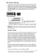
Page 22: ...tions supplied with the wall switch unit Skylight does not open fully The motor system is programmed to only open a skylight to 90 of full opening This is done to protect the hardware from repeated hi...

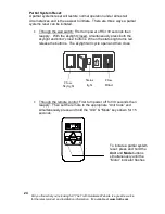
Page 23: ...f the power is not disconnected the DIP switch change may not be recognized System Reset There are times when the motor system operating characteristics can change This can occur for a number of reaso...

Page 24: ...reapply With the skylight closed simultaneously press both the skylight and blind close buttons When the status light turns red release the buttons The skylight will cycle open and then close Through...

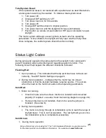
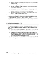
Page 25: ...uring setup and operation the status light on the skylight motor and switch panel if installed will provide information regarding system function The following list will help explain the different con...

Page 26: ...Flashing Green 1 Under normal operation it indicates the rain sensor has been activated The light will flash green only while the skylight is closing 2 Indicates set up mode for the hand held remote S...

Page 27: ...ting Truth Hardware please be aware that Complete product and troubleshooting information is available on our web site at www truth com technicalsupport A qualified electrician is required to resolve...

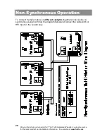
Page 28: ...the latest product and installation information It s available at www truth com 28 Non Synchronous Operation To connect multiple motors on different skylights together none can be on synchronous syst...

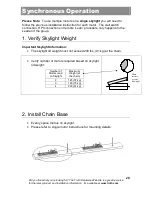
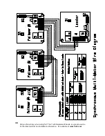
Page 29: ...switch connection HPI connections or remote Learn procedure only happens to the Leader of the group 1 Verify Skylight Weight Important Skylight Information The skylight lid weight must not exceed 200...

Page 30: ...Did you find what you re looking for The Truth Hardware Web site is a great resource for the latest product and installation information It s available at www truth com 30...

Page 31: ...aler or an experienced radio TV technician for help Warning Changes or modifications not expressly approved by Truth Hardware could void the FCC compliance and negate your authority to operate the pro...

Page 32: ...An FKI Industries Company 700 West Bridge Street Owatonna MN 55060 www truth com...

Reviews: