−
0: No configuration
This configuration only occurs in the event of an error,
e.g., if there is no connection to the modules (check
cables) or if an incorrect module type was detected
(check alarm messages).
−
1: Simulator
The system control alone is used and connected mod-
ules are simulated.
−
2: DC-DC only
Only DC-DC modules are connected to the system
control.
−
3: n (AC-DC + m DC-DC)
AC/DC and DC/DC modules are connected to the sys-
tem control.
3. To save the selection: press "Save selection".
4. To restart the TruConvert System Control: press "Restart
CPU".
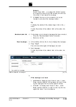
1
Display of the current device
status
2
Main operating parameters
(start page)
3
Device configuration (time and
network settings)
4
Software update
5
Device identification (display
only)
6
Submenu
7
Sidebar (alarm, warning and
event messages)
Start screen
Fig. 7-14
The system is ready for operation: It is in "Idle" mode and
the start screen is displayed.
7
‐
30
System configuration
2020-07-01
A67-0140-00.BKen-0
01-05
Summary of Contents for TruConvert DC 1000 Series
Page 1: ...Operator s manual TruConvert DC series 1000 TruConvert System Control TruConvert Modular...
Page 2: ......
Page 6: ...II Good to know 2020 07 01 A67 0140 00 BKen 0 01 05...
Page 36: ...3 12 Technical data dependent on device variant overview 2020 07 01 A67 0140 00 BKen 0 01 05...
Page 38: ...7 Ethernet 4 10 8 RS 485 4 11 4 2 Interfaces 2020 07 01 A67 0140 00 BKen 0 01 05...
Page 40: ...Fig 4 3 4 4 Protective earth TruConvert DC series 1000 2020 07 01 A67 0140 00 BKen 0 01 05...
Page 48: ...4 12 RS 485 2020 07 01 A67 0140 00 BKen 0 01 05...
Page 54: ...5 6 CSA certification 2020 07 01 A67 0140 00 BKen 0 01 05...
Page 106: ...16 State diagram State machine Fig 7 19 7 38 State diagram 2020 07 01 A67 0140 00 BKen 0 01 05...


