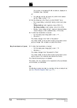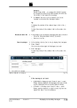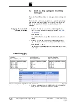
The browser displays the user interface of the TruCon-
vert System Control and the connected modules.
4. Every value entered in the user interface must be confirmed
with enter key
↲
.
1
Input field
2
Value applied in the system
Confirm input
Fig. 7-6
The value applied in the system is then displayed to the
right next to the input field.
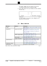
2.2
Menu structure
Main menu
Submenu
Description
>
HOME
—
Start screen
(see "Calling up the web-based user inter-
>
OPERATION
>
Device control DC-DC
(see "Switching the transmission of power on/off",
pg. 7
(see "User interface: displaying and resetting mes-
sages", pg. 7
(see "Display actual values", pg. 7
>
DC-DC module settings
(see "Operating with overload", pg. 7
(see "Set process set values", pg. 7
>
Save settings
>
System configuration
(see "Setting the system configuration", pg. 7
>
CONFIGURATION
—
Base settings for the TruConvert System Control:
(see "Setting the system time", pg. 7
(see "Changing network settings", pg. 7
>
SOFTWARE UPDATE
—
(see "Perform software update", pg. 7
>
DEVICE INFO
—
Information on device identification
Menu structure of the web-based user interface
Tab. 7-1
7
‐
10
Operation via web-based user interface
2020-07-01
A67-0140-00.BKen-0
01-05
Summary of Contents for TruConvert DC 1000 Series
Page 1: ...Operator s manual TruConvert DC series 1000 TruConvert System Control TruConvert Modular...
Page 2: ......
Page 6: ...II Good to know 2020 07 01 A67 0140 00 BKen 0 01 05...
Page 36: ...3 12 Technical data dependent on device variant overview 2020 07 01 A67 0140 00 BKen 0 01 05...
Page 38: ...7 Ethernet 4 10 8 RS 485 4 11 4 2 Interfaces 2020 07 01 A67 0140 00 BKen 0 01 05...
Page 40: ...Fig 4 3 4 4 Protective earth TruConvert DC series 1000 2020 07 01 A67 0140 00 BKen 0 01 05...
Page 48: ...4 12 RS 485 2020 07 01 A67 0140 00 BKen 0 01 05...
Page 54: ...5 6 CSA certification 2020 07 01 A67 0140 00 BKen 0 01 05...
Page 106: ...16 State diagram State machine Fig 7 19 7 38 State diagram 2020 07 01 A67 0140 00 BKen 0 01 05...


