19. Enter current-voltage characteristic curve in the "Voltage Cur-
rent Characteristics (VCC) Settings" area
:
−
"VCC Start Point Current [A]": battery current at mini-
mum battery voltage.
−
"VCC End Point Current [A]": battery current upon reach-
ing "VCC End Point Voltage [V]".
−
"VCC End Point Voltage [V]": battery voltage.
The charging and discharging current of a battery are set as
a function of the voltage with the "VCC Settings". The val-
ues must be selected so that they lie in the shaded part of
the VCC curve.
The dashed line shows the "VCC Settings" on delivery
(default values).
VCC curve
Fig. 7-4
20. Check the device status in the upper left corner of the user
interface:
−
"Device status: Idle": Idle: The device is ready for use.
−
"Device status: Error, Power Up": Error: The device is
not ready for use. An alarm message is pending
"Displaying and resetting messages", pg. 7
.
or
Ø
Check status LED 1 on the DC-DC module:
−
LED flashes green: The device is ready for use.
−
LED flashes red: The device is not ready for use. An
alarm message is pending
(see "Displaying and resetting
21. Select >
Operation
>
Device control DC-DC
.
22. Either
Ø
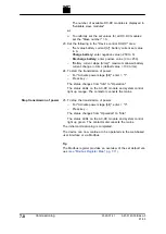
To set the set values for a single DC-DC module: Enter
the number of the slave in the "Device control DC-DC"
area under "Slave module selection".
A67-0140-00.BKen-0
01-05
2020-07-01
Commissioning
7
‐
7
Start transmission of power
Summary of Contents for TruConvert DC 1000 Series
Page 1: ...Operator s manual TruConvert DC series 1000 TruConvert System Control TruConvert Modular...
Page 2: ......
Page 6: ...II Good to know 2020 07 01 A67 0140 00 BKen 0 01 05...
Page 36: ...3 12 Technical data dependent on device variant overview 2020 07 01 A67 0140 00 BKen 0 01 05...
Page 38: ...7 Ethernet 4 10 8 RS 485 4 11 4 2 Interfaces 2020 07 01 A67 0140 00 BKen 0 01 05...
Page 40: ...Fig 4 3 4 4 Protective earth TruConvert DC series 1000 2020 07 01 A67 0140 00 BKen 0 01 05...
Page 48: ...4 12 RS 485 2020 07 01 A67 0140 00 BKen 0 01 05...
Page 54: ...5 6 CSA certification 2020 07 01 A67 0140 00 BKen 0 01 05...
Page 106: ...16 State diagram State machine Fig 7 19 7 38 State diagram 2020 07 01 A67 0140 00 BKen 0 01 05...

