background image

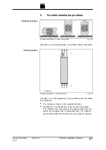
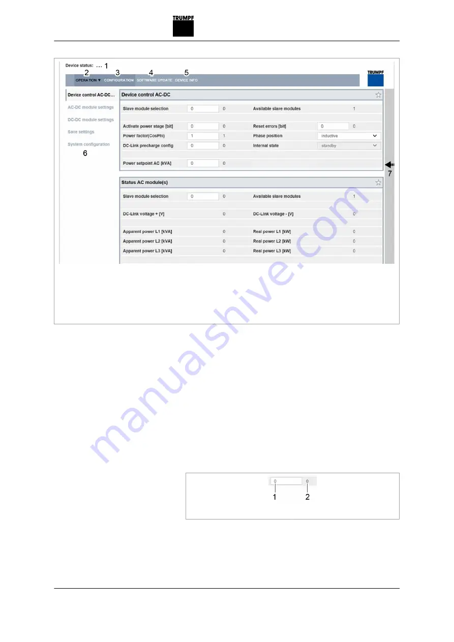
1

Display of the current device 
status

2

Main operating parameters 
(start page)

3

Device configuration (time and 
network settings)

4

Software update

5

Device identification (display 
only)

6

Submenu

7

Sidebar (alarm, warning and 
event messages)

Start screen

Fig. 7-2

The system control balances the set system configuration 
with the actually connected modules. If both values match, 
the start screen of the web-based user interface is displayed.

If the set system configuration ("Expected Configuration") dif-
fers from the automatically detected system configuration 
("Detected Configuration"), the initial commissioning screen 
is displayed again and a message output. Press sidebar (7) 
to display the messages.

12. Select >

Operation

 >

DC Settings

.

13. Every input in the following steps must be confirmed with 

the enter key 

.

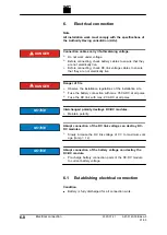
1

Input field

2

Value applied in the system

Confirm input

Fig. 7-3

The value applied in the system is then displayed to the 
right next to the input field.

14. Either

A67-0140-00.BKen-0
01-05

2020-07-01

Commissioning

7

5

Setting process set values 

(DC settings)

Summary of Contents for TruConvert DC 1000 Series

Page 1: ...Operator s manual TruConvert DC series 1000 TruConvert System Control TruConvert Modular...

Page 2: ......

Page 3: ...Operator s manual TruConvert DC series 1000 TruConvert System Control TruConvert Modular Original operator s manual Edition 2020 07 01...

Page 4: ...1 05 Address for orders TRUMPF H ttinger GmbH Co KG Technische Redaktion B tzinger Stra e 80 D 79111 Freiburg Fon 49 761 8971 0 Fax 49 761 8971 1150 Internet http www trumpf huettinger com E Mail info...

Page 5: ...ice depart ment The serial number can be found on the name plate of the device How to reach our Service department 49 761 8971 2170 49 761 8971 1178 Service Elektronik de trumpf com A67 0140 00 BKen 0...

Page 6: ...II Good to know 2020 07 01 A67 0140 00 BKen 0 01 05...

Page 7: ...3 1 3 Warning signs 1 3 2 Using the DC DC module 1 5 3 Authorized personnel 1 6 4 Warning signs on the DC DC module 1 7 5 What you must know as an operator 1 8 6 Dangers from high voltages 1 9 6 1 Pro...

Page 8: ...7 What you must know as an operator 1 10 7 1 Ensuring safe operation of the DC DC mod ule 1 10 7 2 Check periodically 1 10 1 2 Safety 2020 07 01 A67 0140 00 BKen 0 01 05...

Page 9: ...roduct specific docu mentation operating instructions manual etc must be adhered to throughout the entire product lifecycle 1 2 Storing the operating instructions These operating instructions contain...

Page 10: ...dicates a potentially dangerous situation If it is not avoided injuries may occur NOTICE If such a situation is ignored material damage may result Description of the signal words Tab 1 1 1 4 Safety 20...

Page 11: ...ersonal injury and loss of production The operator bears all risks The war ranty is rendered null and void Impermissible uses include for example Use of incorrect components Operation on voltages outs...

Page 12: ...ks It is the duty and responsibility of the operator to maintain the qualifications of the authorized personnel The authorized per sonnel must therefore be trained at regular intervals The following a...

Page 13: ...module 1 Read operating instructions 2 Dangerous voltage 3 Dangerous residual voltage 4 Dangerous battery voltage Warning signs on the DC DC module Fig 1 1 A67 0140 00 BKen 0 01 05 2020 07 01 Warning...

Page 14: ...MPF to request new warning signs Warning sign Meaning This sign indicates that the operat ing instructions must be read Sign warns of hazardous voltage Sign warns of hazardous residual voltage Sign wa...

Page 15: ...ening A person who comes into contact with live DC DC module parts may be killed or severely injured Simultaneous control via web based user interface and Modbus is possible Power transmission stopped...

Page 16: ...module within the conditions descri bed in chapter Technical specifications 3 For the electrical connection use only cables that are in per fect condition and have the correct dimensions 7 2 Check per...

Page 17: ...l fields of application 2 2 2 Function description 2 3 2 1 Operation 2 4 3 Construction 2 5 3 1 TruConvert DC series 1000 construction 2 5 3 2 TruConvert System Control construction 2 7 4 Display elem...

Page 18: ...able battery systems The DC DC module may only be operated in combina tion with intrinsically safe batteries The batteries must be connected in accordance with the applicable local standards The relev...

Page 19: ...speak of batteries in these operating instructions The DC DC module draws energy from a DC link and charges a battery The DC DC module draws energy from a battery and feeds it into a DC link The DC DC...

Page 20: ...s the TruConvert System Control must be con nected upstream In the DC only configuration a TruCon vert System Control can control up to 16 DC DC modules see Fig 2 3 pg 2 4 1 PC with web browser or Mod...

Page 21: ...sed metal housing The fan on the inside of the front panel draws in air for cooling All connecting elements are located on the back side 1 Front panel with mounting brackets 2 Display elements 3 Openi...

Page 22: ...5 6 M6 threaded bolt for connecting the protective earth 7 Cover hood for battery connec tions 8 Threaded bolt minus for bat tery connection 9 Threaded bolt plus for battery connection 10 M6 thread fo...

Page 23: ...et 2 3 Reset button reset IP address 4 No function 5 Display elements TruConvert System Control front side Fig 2 6 1 Connection of 24 V supply volt age 2 Threaded bolt for protective earth 3 RS 485 da...

Page 24: ...g 2 8 Device condition LED Bootloader Initialize Alarm Idling Operation LED1 green on Flashing off Flashing Flashing LED2 yel low Flashing Flashing off off Energy direction Battery charging LED lights...

Page 25: ...al specifications 1 TruConvert DC series 1000 data 3 2 2 TruConvert System Control data 3 8 3 Technical data dependent on device var iant overview 3 10 A67 0140 00 BKen 0 01 05 2020 07 01 Technical sp...

Page 26: ...llowing dimensioning of the rated fuse current IFuse IRated x 1 56 36 A x 1 56 56 16 A The permissible operating voltage of the fuse must be higher than the DC link voltage Fuse ratings UOperation 100...

Page 27: ...plies for the entire range Measuring accuracies Tab 3 3 Description Value Maximum efficiency 97 4 CEC efficiency at 48 V and 800 V Self supply not taken into consid eration 96 7 Efficiency Tab 3 4 Des...

Page 28: ...l life span 10 years Life span Tab 3 6 Description Connection Battery connection plus M8 threaded bolt minus M10 threaded bolt DC link DC Link PCB plug connector 3 pin IPC 16 3 STF 10 16 1969467 from...

Page 29: ...tion Value Dimensions W x H x D incl connection components 216 mm x 132 mm x 515 mm 8 5 x 5 2 x 20 3 Dimensions W x H x D without connection components 216 mm x 132 mm x 456 mm 8 5 x 5 2 x 18 Weight 1...

Page 30: ...ation Dimensional drawing Fig 3 3 Description Value Sound emission level Distance of 1 m from DC DC mod ule 70 dB A Sound emissions Tab 3 9 3 6 TruConvert DC series 1000 data 2020 07 01 A67 0140 00 BK...

Page 31: ...Rated operation TruConvert DC 1010 5 C to 30 C 23 F to 86 F Limited power operation TruConvert DC 1008 40 C to 65 C 104 F to 149 F Limited power operation TruConvert DC 1010 30 C to 65 C 86 F to 149...

Page 32: ...TruCon vert AC 3025 or TruCon vert DC series 1000 RJ 45 Reset button Resetting the IP address Display 3 status LEDs TruConvert System Control interfaces Tab 3 11 Description Value Dimensions W x H x...

Page 33: ...to 65 C 23 F to 149 C 5 90 Up to approx 78 kPa 2000 m high above sea level Pollution degree 2 Storage 20 C to 80 C 4 F to 176 F 5 90 Trans port 20 C to 80 C 4 F to 176 F 90 Environmental conditions T...

Page 34: ...209 A Brief overload while charging discharging for 1 min 1 2 12 kW max 250 A Battery connection maximum values Tab 3 14 1 Certificate mark 2 Material number Name plate of 2582407 DC DC module CSA ma...

Page 35: ...while charging discharging for 10 min 1 2 Brief overload while charging discharging for 1 min 1 2 Battery connection maximum values Tab 3 15 A67 0140 00 BKen 0 01 05 2020 07 01 Technical data dependen...

Page 36: ...3 12 Technical data dependent on device variant overview 2020 07 01 A67 0140 00 BKen 0 01 05...

Page 37: ...oltage 24 V DC TruCon vert DC series 1000 4 5 3 DC link TruConvert DC series 1000 4 6 4 Battery connection TruConvert DC series 1000 4 7 5 Data input data output IN OUT TruCon vert DC series 1000 4 8...

Page 38: ...7 Ethernet 4 10 8 RS 485 4 11 4 2 Interfaces 2020 07 01 A67 0140 00 BKen 0 01 05...

Page 39: ...tective earth connection Protective earth connections Fig 4 1 On the rear side of the housing M6 internal thread On the cover hood M6 threaded bolt The cross section of the protective earth is depende...

Page 40: ...Fig 4 3 4 4 Protective earth TruConvert DC series 1000 2020 07 01 A67 0140 00 BKen 0 01 05...

Page 41: ...must be performed by the customer Supply voltage 24 V DC Fig 4 4 At the DC DC module Phoenix PCB plug connector Required counterpart connector 2 pin 8A CS 3 5 mm Connector for 24 V DC Fig 4 5 External...

Page 42: ...10 16 mm Connector for DC link voltage Fig 4 7 2 x 2 5 mm2 2 x AWG 13 The insulation must exhibit sufficient electric strength Note To keep inductivity at a minimum cables should be twisted All pole...

Page 43: ...ted All pole max 350 A The customer must install suitable separation devices into the connection between the DC DC module and battery The separation devices must comply with applicable standards Indiv...

Page 44: ...ons IN OUT Fig 4 10 RJ 45 male connector Twisted pair patch cable in accordance with standard TIA EIA 568A B CAT 5 or higher Max length 100 m 4 8 Data input data output IN OUT TruConvert DC series 100...

Page 45: ...the customer as close to the housing as possible 24 V supply voltage DC Fig 4 11 Connector for 24 V supply voltage DC Fig 4 12 On the device Phoenix PCB plug connector Required counterpart connector...

Page 46: ...air patch cable in accordance with standard TIA EIA 568A B CAT 5 or higher Max length 100 m Note The total length of the data cable must not exceed 30 m from the PC to the last system control 4 10 Eth...

Page 47: ...onnection Fig 4 14 RJ 45 male connector Twisted pair patch cable in accordance with standard TIA EIA 568A B CAT 5 or higher Max length 30 m A67 0140 00 BKen 0 01 05 2020 07 01 RS 485 4 11 View Connect...

Page 48: ...4 12 RS 485 2020 07 01 A67 0140 00 BKen 0 01 05...

Page 49: ...ation 5 2 2 EU declaration of conformity TruCon vert DC 1008 5 3 3 EU declaration of conformity TruCon vert System Control 5 4 4 CSA certification 5 5 4 1 Location of the CSA mark 5 5 A67 0140 00 BKen...

Page 50: ...ectives Low voltage directive 2014 35 EU Electromagnetic compatibility directive 2014 30 EU Standards taken into account EN 62040 2 2006 AC 2006 EN 62109 1 2010 UL 1741 5 2 CE certification 2020 07 01...

Page 51: ...pply lines of the 24 V supply voltage are equipped with the provided ferrite cores Otherwise class C2 is achieved EU declaration of conformity TruConvert DC 1008 material number 2400760 Fig 5 1 A67 01...

Page 52: ...y lines of the 24 V supply voltage are equipped with the provided ferrite cores Otherwise class C2 is achieved EU declaration of conformity TruConvert System Control material number 2418064 Fig 5 2 5...

Page 53: ...C22 2 No 107 1 16 UL 1741 Second Edition IEC62109 1 First Edition National Differences UL62109 1 IEC 62109 1 2010 EN 62109 1 2010 4 1 Location of the CSA mark If the name plate of the device bears th...

Page 54: ...5 6 CSA certification 2020 07 01 A67 0140 00 BKen 0 01 05...

Page 55: ...ng the delivery 6 3 2 Unpacking 6 4 2 1 Disposing of packaging material 6 4 3 Transport storage 6 5 3 1 Transport 6 5 3 2 Storage conditions 6 5 4 Requirements for the site 6 6 5 Possible installation...

Page 56: ...6 8 6 2 Connection diagram with 3 DC DC modules example 6 11 7 Dismantling 6 12 7 1 Dismantling the DC DC module 6 12 8 Shipping 6 13 8 1 Shipping the module 6 13 9 Disposal 6 14 9 1 Disposing of the...

Page 57: ...mpleteness in accordance with the delivery note and also for visible damages incurred during transport 2 In order to retain the right of recourse report any shipping damages immediately in writing to...

Page 58: ...aterial If you do not want to keep the packaging material for a subse quent transport Dispose of all packaging materials in compliance with the rel evant regional waste disposal regulations 6 4 Unpack...

Page 59: ...TRUMPF 2 Maintain specified environmental conditions 3 2 Storage conditions If you do not install the module immediately following delivery 1 Store the module in original packaging If the original pa...

Page 60: ...at the air flow rate must be multiplied by the number of devices if several modules are operated Air short circuits and mutual interference of the modules must be prevented Number of modules Air flow...

Page 61: ...on is only permitted under the follow ing conditions The cooling air moves in the upwards direction Installation of a collection tray under the DC DC module The collection tray must prevent any glowin...

Page 62: ...Fuse the battery connection with max 350 ADC at all poles Fuse the DC link with max 20 ADC at all poles Interchanged polarity destroys DC DC modules Maintain polarity Abrupt connection of the DC link...

Page 63: ...e 8 Nm 2 Screw protective earth to the threaded bolt on the cover hood Max torque 8 Nm 3 Screw protective earth on TruConvert System Control Max torque 2 Nm 4 Fully discharge the battery and ensure ab...

Page 64: ...tput of the DC DC module to the IN data input of the next DC DC module Connect the terminating resistor to the OUT data out put of the last DC DC module 13 Connect the TruConvert System Control to the...

Page 65: ...minating resistor Connection diagram example with 3 DC DC modules Fig 6 5 Note The terminating resistor must be connected to the last bus par ticipant to ensure data transmission The terminating resis...

Page 66: ...ttery cannot be discharged open separators on the battery 2 De energize the connection cables to the DC link voltage 3 De energize the connection cables to the 24 V supply volt age 4 Unscrew connectio...

Page 67: ...se packaging material which can withstand transport stresses to ship the module If the original packaging is no longer available Suitable packaging material can be purchased from TRUMPF A67 0140 00 BK...

Page 68: ...9 Disposal 9 1 Disposing of the module Observe the local regulations when disposing of the module 6 14 Disposal 2020 07 01 A67 0140 00 BKen 0 01 05...

Page 69: ...r interface 7 9 2 1 Calling up the web based user interface 7 9 2 2 Menu structure 7 10 3 Operation via Modbus 7 11 3 1 Establishing a connection 7 11 3 2 Modbus Register Map 7 11 4 Transmission of po...

Page 70: ...alues 7 26 8 1 Set process set values 7 26 9 Data backup 7 28 9 1 Saving data 7 28 10 System configuration 7 29 10 1 Setting the system configuration 7 29 11 System control 7 32 11 1 Setting the syste...

Page 71: ...e same address range on the PC as on the TruCon vert System Control 192 168 1 3 On the PC set the last block of the IP address Do not set the same address as on the TruConvert Sys tem Control IP addre...

Page 72: ...resent system configu ration 0 No configuration This configuration only occurs in the event of an error e g if there is no connection to the modules check cables or if an incorrect module type was det...

Page 73: ...splayed If the set system configuration Expected Configuration dif fers from the automatically detected system configuration Detected Configuration the initial commissioning screen is displayed again...

Page 74: ...C module in the DC Volt age Alarm Thresholds area Minimum Battery Voltage Threshold V lower limit up to which the battery is discharged If this value is not met e g due to short circuit of the battery...

Page 75: ...VCC curve Fig 7 4 20 Check the device status in the upper left corner of the user interface Device status Idle Idle The device is ready for use Device status Error Power Up Error The device is not re...

Page 76: ...tage bit enter 1 Press key The status changes from Idle to Operation The status LEDs on the AC DC module and system control light up orange The contactor connects the mains 25 To stop the transmission...

Page 77: ...on the PC 3 Enter IP address of the TruConvert System Control in the address line IP address of the TruConvert System Control on delivery 192 168 1 2 1 Display of the current device status 2 Main oper...

Page 78: ...ansmission of power on off pg 7 16 see User interface displaying and resetting mes sages pg 7 18 see Display actual values pg 7 24 DC DC module settings see Operating with overload pg 7 22 see Set pro...

Page 79: ...on Condition Initial commissioning was performed see Commissioning pg 7 3 1 Connect the TruConvert System Control to the Modbus mas ter with an Ethernet cable 2 To switch on the system control and the...

Page 80: ...rs to factory settings bit 0 0 1 UIN T16 Coil 1 01 05 1016 Timeout for com munication s 1 0 10 1 UIN T16 Regi ster 1 03 06 1017 Setting this flag will restart the CPU only in Idle or Error State 0 0 1...

Page 81: ...100 UIN T16 Regi ster 1 04 Alarm and warning messages Tab 7 5 Process set values Addr Lengt h Data type F Code read F Code write Description Unit Reso lution Defaul t Min max 4000 1 coil UINT 16 01 05...

Page 82: ...ase W 1 0 8000 0 1200 0 4124 1 reg UINT 16 03 06 Max battery voltage alarm limit V 0 1 750 0 750 4127 1 reg UINT 16 03 06 Min battery voltage alarm limit V 0 1 0 0 700 4500 1 reg INT 16 03 06 Battery...

Page 83: ...rrent 8 Max battery voltage 16 Min battery voltage multi mode display possible 1 5126 1 reg 04 Overload capacity 0 1 5127 1 reg 04 DC link voltage V 1 0 5300 32 reg STRIN G 03 Status of the limiting c...

Page 84: ...slave to be addressed see Tab 7 6 pg 7 14 Note User interface and Modbus have different scaling For example 100 A ms 100 on user interface 10000 in Modbus 2 Enter set value for the battery current in...

Page 85: ...stopping power transmission for other DC DC mod ules Select another DC DC module via user interface or slave address via Modbus and perform the previous steps again or To switch on all DC DC modules s...

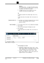
Page 86: ...3 Save messages as list 4 Alarm and warning messages 5 Display hide messages by type Sidebar expanded Fig 7 8 A message consists of 3 components Code message number Source originator and message text...

Page 87: ...idebar click on the icon to display the messages 4 Press Reset The icon turns white again All messages are reset 5 Hide messages To hide the window of the sidebar click on the active icon again 1 Icon...

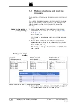
Page 88: ...7 13 Slave address 0 The number of all messages that occurred in the system is output 2 Read out the number of current alarm warning info mes sages that have occurred on an individual DC DC module Sl...

Page 89: ...m and were caused by the respective DC DC module The address represents the message num ber that was stored there in the overview list slave address 0 The value stored at this address can be 0 or 1 Va...

Page 90: ...is regulated accordingly by the system Note Overload operation is only possible in the overload temperature range from 5 C to 40 C and with a battery voltage 30 V 1 To select the same settings for all...

Page 91: ...oad capacity increases again and overload operation is possible again 6 2 Examples Reduce and then again increase overload capacity The overload capacity drops from 100 to 0 if the system is operated...

Page 92: ...the current battery values User interface Select Operation Device Control DC DC Read the actual values in the Status Battery Interface area Modbus Read actual values see Tab 7 7 pg 7 15 3 Display cur...

Page 93: ...er interface Select Operation Device Control DC DC Read the actual value in the Device Temperature area Modbus Read actual value see Tab 7 7 pg 7 15 A67 0140 00 BKen 0 01 05 2020 07 01 Actual values 7...

Page 94: ...ery is charged Modbus see Tab 7 6 pg 7 14 3 Set the lower and upper alarm limit User interface Enter the limit values for the DC DC module in the DC Voltage Error Thresholds area For DC Voltage Limits...

Page 95: ...ee Fig 3 1 pg 3 4 User interface Set the following in the Voltage Current Characteristics VCC Settings area VCC Start Point Current A battery current at mini mum battery voltage VCC End Point Current...

Page 96: ...in the TruConvert System Control 3 In the Save settings area select Restore factory settings to again restore the factory settings 4 Press Export settings to save the current settings as a CSV file on...

Page 97: ...igura tion is displayed as the sug gested value 2 Most recently saved configura tion 3 Most recently saved configura tion does not match the detected configuration Input screen System Configuration Fi...

Page 98: ...DC and DC DC modules are connected to the sys tem control 3 To save the selection press Save selection 4 To restart the TruConvert System Control press Restart CPU 1 Display of the current device stat...

Page 99: ...displayed If the set system configuration Expected configuration dif fers from the automatically detected system configuration Detected configuration the input screen System configu ration is display...

Page 100: ...e see Tab 7 3 pg 7 12 11 2 Changing network settings Note The IP address can only be changed via the user interface 1 Select CONFIGURATION Server Configuration 2 Enter new values in IP Adresse IP addr...

Page 101: ...n to restart the system The IP address of the TruConvert System Control is reset to 192 168 1 2 7 To change the network settings User interface Enter new values for IP Subnet Mask IP Host and IP Gatew...

Page 102: ...th new software stored on PC 1 Select SW update 2 In the Software update area press the button and open the zip file 3 Press the button to upload the zip file If the update was performed successfully...

Page 103: ...Package area read the details on the installed software package Relevant details are Integration Level and Buildnumber 5 The software version on the system control can be read in the Software System...

Page 104: ...1 in frequently needed areas 2 To display the created favorites page click on the star at the top in the menu bar 3 1 Click the prohibition symbol to delete area from the favor ites 2 Click arrow to m...

Page 105: ...isplay search field 2 Enter keyword 3 Result of the search Search Fig 7 18 1 Click on the magnifying glass at the top in the menu bar 1 2 Enter the keyword in the search field 2 Press key All areas th...

Page 106: ...16 State diagram State machine Fig 7 19 7 38 State diagram 2020 07 01 A67 0140 00 BKen 0 01 05...

Page 107: ...enance 1 Maintenance work 8 2 1 1 Periodic check of the environmental condi tions 8 2 1 2 Exchanging fans 8 2 1 3 Performing software updates 8 2 1 4 Cleaning 8 2 A67 0140 00 BKen 0 01 05 2020 07 01 M...

Page 108: ...ssible 1 2 Exchanging fans The operating hours of the fan are counted After the allowed running period is up the module outputs a message TRUMPF recommends replacing the ventilator after an operation...

Page 109: ...Chapter 9 Troubleshooting 1 Fault indication and messages 9 2 1 1 Fault indication with the LEDs 9 2 2 Messages 9 3 A67 0140 00 BKen 0 01 05 2020 07 01 Troubleshooting 9 1...

Page 110: ...nterface Via the Modbus 1 1 Fault indication with the LEDs 1 Front side TruCon vert DC series 1000 2 Rear side TruCon vert DC series 1000 3 TruConvert System Control front side Status LEDs Fig 9 1 LED...

Page 111: ...ting the device with the web based user interface the alarm and warning numbers are displayed together with the message text In case of control with Modbus only the numbers and no text are transmitted...

Page 112: ...upply undervoltage DC DC module 60145 Wrong polarity on DC terminal detected DC DC module 60132 RS485 communication alarm DC DC module 60129 Battery voltage under threshold setting DC DC module 60150...

Reviews: