46
7200790 Service Manual for the HELION
®
XENION
®
Surgical Lighting System GB
14 Functional Check, Hand-Over and Customer Instruction
B Fixed lamp
RR
imax
= 0.3 ohms
The measuring method via the external earthed con-
ductor should only be used if the ceiling connection is
later no longer accessible, e.g. in the case of a lami-
nar flow ceiling system. The prerequisite for this is that
(initial installation) point 5 and the resistance value
between point 2 and 5 are documented at the first
acceptance. Thereafter, the following can be obser-
ved during each subsequent repeat measurement:
• If necessary, measure the resistance between the
main earthed conductor connection (2) and the
nearest earthed conductor connection (5).
• In this case, document the location of the exter-
nally accessible earthed conductor (5) and enter
the measurement between this place and the main
earthed conductor connection (2) in the test re-
port.
• After assembly of the lamp or lamp combination,
measure the resistance between point 2 and/or
point 5 and all metal parts of the lamp and enter
the highest reading in the test report.
Testing the support system
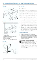
• Checking and securing the retaining screws
-
Check the correct assembly and fixing of the six
retaining screws of the moving arm on the ceiling
tube and the four retaining screws of the spring
arm on the moving arm.
WARNING – Falling lighting system:
The moving and spring arms are very heavy
and can fall once the retaining screws
shown in Figure 7 have been unscrewed!
-
If necessary, replace any missing retaining screws
and/or fix the screws consecutively with Loctite
screw-locking adhesive.
Figure 05
Figure 06
1 Mains supply
2 Main earthed conductor connection
3 Measuring instrument
4 Instrument leads
5 Externally accessible earthed conductor
Figure 07

