42
7200790 Service Manual for the HELION
®
XENION
®
Surgical Lighting System GB
13 Testing the Electrics of the XENION M/M+ / L/L+ Lamp
13.2
13.2
13.2
13.2
13.2 If the dimmer is defective
If the dimmer is defective
If the dimmer is defective
If the dimmer is defective
If the dimmer is defective
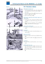
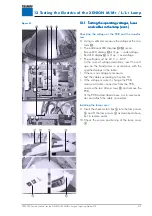
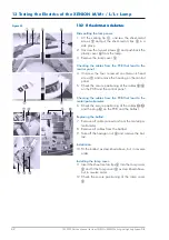
Dismantling the lamp cover:
1. Lift the sealing lip
1
, unscrew the sheet-metal
screws
2
and put the sheet-metal clips
5
in a
safe place.
2. Unscrew the two set screws
4
and push back the
plastic cover
6
from the lamp.
3. Remove the lamp cover
3
.
Checking the cables from the PCB that lead to the
control panel:
4. Unscrew the four recessed countersunk head
screws
7
and remove the housing on the control
panel.
5. Check the secure positioning of the cables
8
/
9
on the PCB and the control panel.
Checking the cables from the PCB that lead to the
motor/potentiometer:
6. Check the secure positioning of the cables
A
/
D
and the plug
C
on the PCB and the ballast.
Replacing the ballast:
7. Remove all cable connectors from the motor/po-
tentiometer.
8. Remove all cables from the ballast.
9. Take off the hexagon nut
B
and remove the bal-
last.
Installation:
10.Fit the ballast as described above, but in reverse
order.
Installing the lamp cover:
11.Insert the sheet-metal clips
5
into the lamp cover
3
and fit the lamp cover
3
as described above,
but in reverse order.
12.Check the secure positioning of the lamp cover
3
.
Figure 03


