41
7200790 Service Manual for the HELION
®
XENION
®
Surgical Lighting System GB
13.1
13.1
13.1
13.1
13.1 TTTTTesting the operating voltages, fuses
esting the operating voltages, fuses
esting the operating voltages, fuses
esting the operating voltages, fuses
esting the operating voltages, fuses
and cables in the lamp (cont.)
and cables in the lamp (cont.)
and cables in the lamp (cont.)
and cables in the lamp (cont.)
and cables in the lamp (cont.)
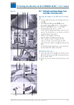
Checking the voltage at the PCB and the transfor-
mer:
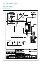
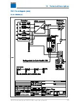
8. Using a voltmeter, measure the voltage at the con-
tacts
A
:
• The additional LED displays
D
/
E
mean:
-
Green LED display
D
is lit up = undervoltage
-
Red LED display
E
is lit up = overvoltage
• The voltage must be 24 V +/-0.5 V.
-
In the case of voltage deviations, reset the volt-
age on the transformer in accordance with the
specified values in the table.
• If there is no voltage to measure:
-
Test the cables according to Section 10.
• If the voltage is correct, change the PCB:
-
remove all cable connectors from the PCB,
-
unscrew the two Allen screws
F
and remove the
PCB,
-
fit the PCB as described above, but in reverse or-
der and attach the cable connectors.
Installing the lamp cover:
9. Insert the sheet-metal clips
5
into the lamp cover
3
and fit the lamp cover
3
as described above,
but in reverse order.
10.Check the secure positioning of the lamp cover
3
.
Figure 02
13 Testing the Electrics of the XENION M/M+ / L/L+ Lamp

