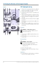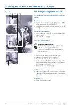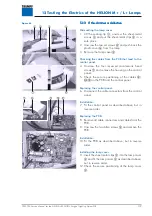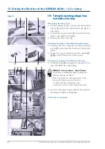
26
7200790 Service Manual for the HELION
®
XENION
®
Surgical Lighting System GB
9 Testing the Input Voltages
9.1
9.1
9.1
9.1
9.1
TTTTTesting the input voltage of the trans
esting the input voltage of the trans
esting the input voltage of the trans
esting the input voltage of the trans
esting the input voltage of the trans-----
former
former
former
former
former
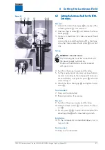
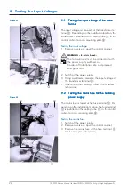
The input voltage is measured at the transformer ter-
minal
1
. Depending on the installation location, the
transformer is installed on the ceiling tube
2
, in the
control cabinet or on a mounting plate
3
.
Testing the input voltage:
1. Remove covers etc, open the control cabinet.
WARNING – Electric Shock:
The following test must be carried out with
the power supply switched on.
Cordon off installation site and proceed
with great care.
2. Switch on the power supply.
3. Using a voltmeter, measure the input voltage at
the transformer terminal
1
:
• If there is no input voltage, inform the customer’s
technicians.
9.2
9.2
9.2
9.2
9.2
TTTTTesting the mains fuse for the building
esting the mains fuse for the building
esting the mains fuse for the building
esting the mains fuse for the building
esting the mains fuse for the building
power supply
power supply
power supply
power supply
power supply
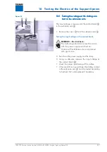
The mains fuse is tested at the fuse terminal
1
. De-
pending on the installation location, the fuse terminal
1
is installed on the ceiling tube
2
, in the control
cabinet or on a mounting plate
3
.
Testing the mains fuse:
1. Switch off the power supply.
2. Remove covers etc, open the control cabinet.
3. Remove the mains fuse at the fuse terminal
1
,
test it and replace if necessary.
Figure 01
Figure 02

