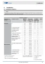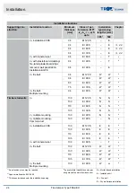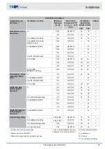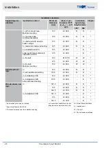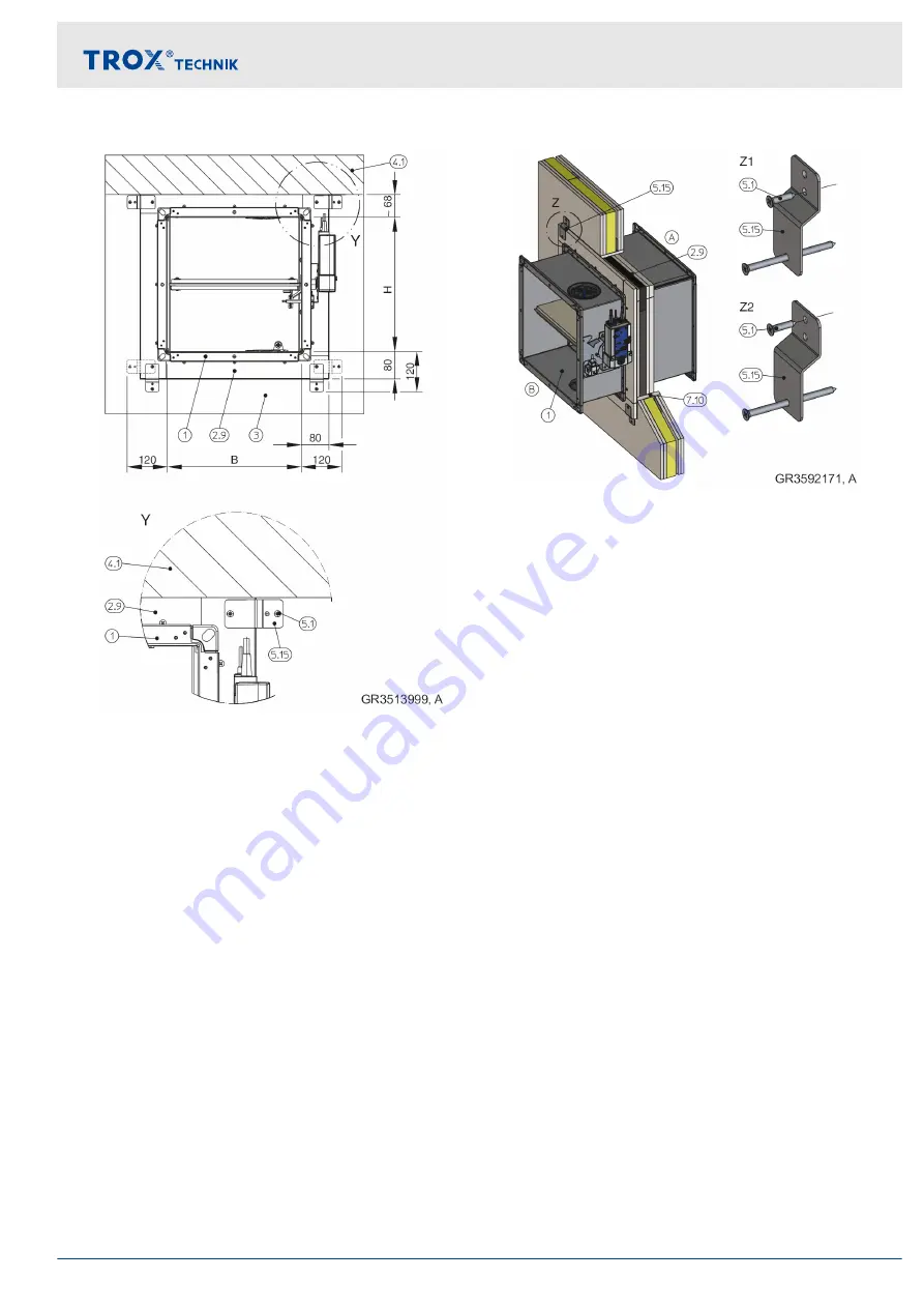
Fig. 17: Installation kit – free space (for installation near
the floor or ceiling)
1
FKA2-EU
2.9
Installation kit ES (cover plate, shortened by
others)
3
Wall
4.1
Solid ceiling slab / solid floor
5.1
Dry wall screw, to be provided by others
5.15 Bracket
Fig. 18: Fastening the installation kit to the stud frame
1
FKA2-EU
2.9
Installation kit ES
5.1
Dry wall screw, to be provided by others
5.15 Bracket
7.10 Trim panels
Z1
Fastening – with or without simple trim panels
Z2
Fastening – with double trim panels
Installation with installation kit WA on solid walls
and ceiling slabs
Casing length L = 500 mm
The installation kit must be mounted on the fire
damper by others.
Enough clear space is required to attach the instal-
lation kit to the wall, at least 150 mm around the
perimeter Cladding and wall / ceiling connection
must be made on 4 sides.
The fire damper is flanged onto a sheet steel duct
shortened so as to be flush-mounted in the wall/
ceiling.
The fire damper is fixed to the wall / ceiling slab and
the cladding is fixed with suitable wallplugs with suit-
ability certificate for fire resistance, alternatively
using push through installation.
For additional installation details see corresponding
installation situation.
Installation
General installation information
Fire damper Type FKA2-EU
33

