18
DC7000 ANTIQUE
MAINTENANCE
(The following maintenance procedure must be
carried out for commercial and health care
premises, but is not necessarily required for
domestic installations).
Maintenance of the unit is required to ensure
continued performance after installation and that
it continues to provide scald prevention.
The frequency of routine maintenance of the
internal of the valve will depend mainly on the
water supply condition. Local knowledge will
dictate suitable intervals. In addition, the following
precautions should be observed:
a)
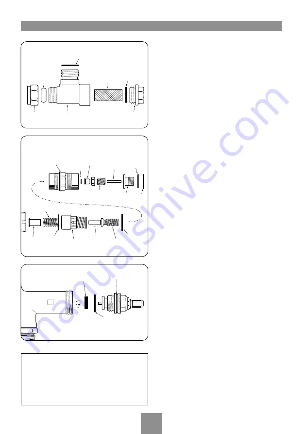
Initially check the strainer baskets (fig.33) for
debris once every three months and clean if
necessary. This period can be increased if
appropriate once the general condition and
cleanliness of the water is established. Where the
water supplies come from beneath (rising) the
mixer valve, lifting out the strainer basket may not
remove all of the trapped debris. Full flushing out
may be necessary if debris is found or suspected.
b)
Perform a thermal shut off test every three
months, and check the maximum temperature
setting. See the ‘Commissioning’ section for the
details of this test and re-adjustment of the
maximum temperature setting if required.
c)
If the maximum water temperature varies by
more than 2°C from the commissioned setting
then ensure the strainers are clean and that the
isolating valves are fully open. Test the non return
valves as described below. If these tests do not
highlight the reason for the temperature variation,
then follow the procedure below for investigating
failure of the thermal shut off test.
d)
If the mixer valve fails the thermal shut off
test then remove the knobs, faceplate and control
valve cover. Check the internal surface for scaling.
If the body requires descaling then it should be
removed from the pipework to carry this work out
– the valve should be able to be removed through
the aperture without breaking tiles. All rubber
parts must be removed prior to descaling. The
slide valve seal (fig.34) located inside the body
should always be replaced with a new seal after
removal. Maintenance kits are available which
contain ‘O’ rings and/or the thermostatic element.
Inlet strainer body
Strainer
basket
Swivel
seal
15mm
ferrule
15mm
compression
nut
End cap
Cap seal
On/off unit
Seal
Retaining nut
1/2" Washer
Fig.33
Valve cover
Piston
seal
Temp
adjustment
piston
Control
stem
Max temp
adjustment
screw
Temp knob
adaptor
Thrust
washer
Adaptor
circlip
Baffle
tube
Return
spring
Slide valve
seal
Slide valve
sub assembly
Thermostat
element
Element
spring
Valve cover
seal
Fig.35
Fig.34
When cleaning the external faceplate and
knobs, never use cleaners containing
abrasives or solvents as they may damage
the chrome plating. Use only soap and a
soft cloth.
Summary of Contents for DC7000 Antique
Page 2: ...DC7000 ANTIQUE UKAS QUALITY MANAGEMENT 003...
Page 25: ...23 DC7000 ANTIQUE...
Page 26: ...DC7000 ANTIQUE 24...
Page 27: ......


