background image

Due to continuous improvement, Triatek reserves the right to change product specifications without notice.

MOUNTING/WIRING

HMS-1650

Power

26 

-

Triatek reserves the right to change product specifications without notice.

Triatek reserves the right to change product specifications without notice.

Summary of Contents for HMS-1650

Page 1: ...HMS 1650 Installation Manual Version 03 06 17 Triatek HMS 1650 Fume Hood Controller ...

Page 2: ...ut Range zero based or offset Occupied Mode Setpoint Unoccupied Mode Setpoint Standby Mode Setpoint Analog Output Operating Mode Direct or PID Analog Output Range zero based or offset Analog Output Upper Limit 0 100 Analog Output Lower Limit 0 100 Analog Output Input Channel AI 1 thru AI 4 TI 1 or TI 2 Analog Output Action Direct or Reverse Analog Output Range zero based or offset Flow Range Maxim...

Page 3: ... 0 0 100 0 Alarm Limits Occupied Mode High Alarm Setpoint Occupied Mode High Warning Setpoint Occupied Mode Low Warning Setpoint Occupied Mode Low Alarm Setpoint Unoccupied Mode High Alarm Setpoint Unoccupied Mode High Warning Setpoint Unoccupied Mode Low Warning Setpoint Unoccupied Mode Low Alarm Setpoint Audible Alert Enabled Input Channels AI 1 thru AI 4 TI 1 TI 2 Operating Mode audible or sile...

Page 4: ...roduct specifications without notice Warning Failure to follow the wiring diagrams could result in damage to your equipment and could void your warranty Wiring diagrams can also be found at www triatek com Under no circumstances should a single transformer be split between actuator and controller Doing so will damage the actuator the transformer the controller or all units A single 120 24V 30Va tr...

Page 5: ... Sensors 23 Analog Input Sash Position Sensor 24 Digital Input Occupancy Sensor 25 Power 26 Isolated Power Supply 27 COMMUNICATIONS BACnet MS TP 28 Metasys N2 Open 29 BASIC PROGRAMMING 31 33 Introduction 31 MainDisplayScreen 31 32 Configuring Fume Hood Monitor 32 Configuring Analog Output for Exhaust Damper Control 32 Calibrating Face Velocity Sensor 32 Configuring Face Velocity Setpoints 32 Confi...

Page 6: ...4VDC Control Signal Wire Size 18 AWG minimum Power Supply Class 2 24Vac 10 30VA universal 120 240 to 24 Vac 60 50 Hz step down isolation transformer provided Communications BACnet MS TP network Two wire Twisted Pair RS 485 signaling Metasys N2 network Two wire Twisted Pair RS 485 signaling Recommended Cable Type Belden 1325A Touchscreen User Interface LCD Size 3 2 diagonal LCD Type Transmissive Re...

Page 7: ...F Venturi Valve Order Separately Diameter 6 8 10 12 14 16 O D CFM Range 30 2400 Materials Aluminum Stainless Steel Heresite Coating Sound Insulation Optional Actuation Electronic or Pneumatic Part Number Guide 7 HMS 1650 Triatek reserves the right to change product specifications without notice GENERAL Specifications Accuracy is 5FPM when velocity drops below 60FPM or exceeds 140 FPM HMS1650 1 1 S...

Page 8: ...en the face velocity is outside defined acceptable limits The face velocity ranges for these conditions are easily set by the user for the specific installation when necessary The background color changes provide an overview of the monitored fume hood face velocity conditions at a glance Alarm conditions may be defined by the user in terms of desired face velocity settings for the fume hood being ...

Page 9: ...lock Switch may be used to further control access to change in operating modes The HMS 1650 provides a unique set of built in diagnostics tools that are extremely valuable for facilitating the troubleshooting process during the installation and commissioning phase Included in these built in diagnostics tools are Manual Override capabilities for both analog outputs and relay outputs and a comprehen...

Page 10: ...4 See page 12 for mounting details for the HMS 1650 display unit The preferred location is eye level usually on one of the side bezel panels Please note that the display unit is cable connected to the control unit and provision must be made to route the cable without interference with the fume hood sash or sash cable The control unit is typically secured in a convenient location on top of the fume...

Page 11: ...NTING WIRING HMS 1650 11 Right Side View Left Angle Side View HMS Case Dimensions Triatek reserves the right to change product specifications without notice Recommended Cable Type Belden 1325A Control Unit ...

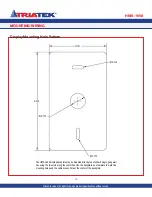
Page 12: ...e Pattern HMS 1650 Triatek reserves the right to change product specifications without notice 12 The HMS 1650 display backplate may be mounted directly to a standard single gang wall box using the two slots along the centerline Use the backplate as a template to mark the mounting holes and the cable access hole at the center of the backplate ...

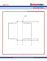
Page 13: ...MOUNTING WIRING Controller Mounting Hole Pattern HMS 1650 Triatek reserves the right to change product specifications without notice 13 ...

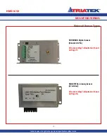
Page 14: ...e to properly identify the sensor that came with your HMS controller could result in incorrect wiring and sensor damage Make sure you use the correct wiring sequence for the sensor you received For reference photos of both types of sensors are provided on the following page If unsure as to which type of sensor you have and or how to properly wire the sensor you received contact the factory at 888 ...

Page 15: ...Triatek reserves the right to change product specifications without notice 15 SENSIRION Digital Sensor Standard 9 Pin Wire According To Illustration Found on Page 17 HONEYWELL Analog Sensor 3 Terminal Wire According To Illustration Found on Page 18 ...

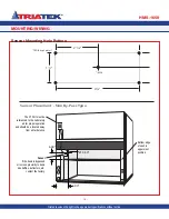
Page 16: ... specifications without notice 16 2 3 16 43 8 1 8 DIA typ 4 places 3 8 DIA Sensor Placement Non By Pass Type 11 2 6 00 6 00 Ø 0 50 The P1 Port must be referenced to the Laboratory air for proper operation and should be a located away from air turbulence Bottom edge of sash in uppermost position Sensor If the hood is bypassed or in close proximity to items like baffles deflectors etc contact the fa...

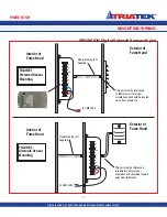
Page 17: ...ing Interior of Fume Hood Flexible Tubing 3 ft Supplied To HMS 1650 This port must be referenced to laboratory air for proper orientation and should be located away from turbulence Exterior of Fume Hood FIGURE 1 Preferred Sensor Mounting Interior of Fume Hood Flexible Tubing 3 ft Supplied This port must be referenced to laboratory air for proper orientation and should be located away from turbulen...

Page 18: ...ood To HMS Control Unit To HMS Control Unit Interior of Fume Hood Exterior of Fume Hood Exterior of Fume Hood Flexible Tubing 3 FT Supplied This port must be referenced to Laboratory air for proper operation and should be located away from air turbulence Flexible Tubing This port must be referenced to Laboratory air for proper operation and should be located away from air turbulence Attach louvere...

Page 19: ...MOUNTING WIRING Notes HMS 1650 19 Triatek reserves the right to change product specifications without notice ...

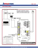
Page 20: ...atek reserves the right to change product specifications without notice 20 NOTE If using Honeywell sidewall sensor module the three terminals are IN and G The terminal should be connected to 10V IN should be connected to AI_1 and G should be connected to AGND at the HMS 1650 backplane Controller Configuration Dipswitch Settings S1 1 OFF S1 5 OFF AI 1 set as 0 5V Input ...

Page 21: ... to Electric Actuator NOTE If using Honeywell sidewall sensor module the three terminals are IN and G The terminal should be connected to 10V IN should be connected to AI_1 and G should be connected to AGND at the HMS 1650 backplane Controller Configuration Dipswitch Settings S1 1 OFF S1 5 OFF AI 1 set as 0 5V Input ...

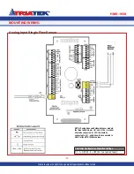
Page 22: ...ice 22 MOUNTING WIRING Analog Input Single Flow Sensor NOTE If using Honeywell sidewall sensor module the three terminals are IN and G The terminal should be connected to 10V IN should be connected to AI_1 and G should be connected to AGND at the HMS 1650 backplane Triatek reserves the right to change product specifications without notice Controller Configuration Dipswitch Settings S1 1 OFF S1 5 O...

Page 23: ...GND at the HMS 1650 backplane Triatek reserves the right to change product specifications without notice Controller Configuration Dipswitch Settings S1 1 OFF S1 5 OFF AI 1 set as 0 5V Input S1 2 OFF S1 6 OFF AI 2 set as 0 5V Input NOTE If using Honeywell sidewall sensor module the three terminals are IN and G The terminal should be connected to 10V IN should be connected to AI_1 and G should be co...

Page 24: ...50 Due to continuous improvement Triatek reserves the right to change product specifications without notice 24 MOUNTING WIRING Analog Input Sash Position Sensor Triatek reserves the right to change product specifications without notice Controller Configuration Dipswitch Settings S1 2 OFF S1 6 ON AI 2 set as 0 10V Input ...

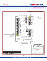
Page 25: ...ING WIRING HMS 1650 25 Digital Input Occupancy Sensor Triatek reserves the right to change product specifications without notice Controller Configuration Slideswitch Settings S5 Left Active Low Digital Input ...

Page 26: ... continuous improvement Triatek reserves the right to change product specifications without notice MOUNTING WIRING HMS 1650 Power 26 Triatek reserves the right to change product specifications without notice ...

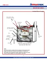
Page 27: ...r provided with HMS 1650 Only Class 2 wiring in this compartment Note This product should be installed with the manufacturer provided isolated power supply and connected to an electrical circuit protected by a minimum 20A circuit breaker This circuit breaker should be mounted in an approved electrical enclosure located separately but in close proximity to this product 240 VAC 50 60 Hz Blue Slow Bl...

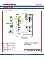
Page 28: ... Wiring HMS 1650 28 Controller Configuration Dipswitch Settings S3 7 ON S3 8 ON BACnet MS TP protocol selected Triatek reserves the right to change product specifications without notice NOTE For optimum network communications the reference signal REF must be connected to the NETWK REF terminals at the backplane IN NETWK ___ REF OUT ...

Page 29: ...nge product specifications without notice NOTE For optimum network communications the reference signal REF must be connected to the NETWK REF terminals at the backplane Controller Configuration Dipswitch Settings S3 7 ON S3 8 OFF Metasys N2 Open protocol selected IN NETWK ___ REF OUT ...

Page 30: ...o continuous improvement Triatek reserves the right to change product specifications without notice COMMUNICATIONS Notes HMS 1650 30 Triatek reserves the right to change product specifications without notice ...

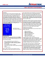
Page 31: ...ired setpoint and is in the caution range A red background indicates that the current face velocity has reached a critical condition and is outside of the allowable limits of the desired setpoint The HMS 1650 incorporates a full color touchscreen and includes an extensive easy to use menu system that allows the user to quickly setup the fume hood controller for immediate use Also integrated into t...

Page 32: ...d to achieve approximately 100 ft min at the sash opening with the sash positioned at a height of 18 inches An air flow measuring instrument should be used to confirm that the face velocity is approximately 100 ft min Move the analog output slider to increase or decrease the effective face velocity at the sash opening and then click the Next button to proceed to the next field calibration screen U...

Page 33: ...ingly Once the sash stops moving the PID control loop resumes using the sidewall sensor to fine tune the face velocity to meet the target setpoint Selecting the Sash Control option on the Sash Setup menu invokes the sash width configuration screen where the width of the sash opening may be specified in inches This width is used in conjunction with the height of the sash opening to calculate the ef...

Page 34: ... specific information may be individually suppressed by selecting Display Setup Display Options and deselecting the status information that should be disabled For those customers who need support for multiple languages the Language Options selection allows the user to change the language displayed in the menu system and on the main display screen Changing the time and date can be accomplished eith...

Page 35: ...calibration ON Auto calibration 3 Reserved 4 Reserved Options Dipswitch S2 mode configuration 1 1 Product Type OFF FMS HMS ON CMS 1650 2 MAX FLOW Button OFF Disabled ON Enabled 3 Mode Select OFF FMS 1650 CMS 1650 ON HMS 1650 4 Operational Mode OFF Demo Mode ON Run Mode Pushbutton Switch SW1 Reset Button Pushbutton Switch SW2 Reserved Triatek reserves the right to change product specifications with...

Page 36: ...S 1650 for sidewall velocity sensor set dipswitch positions 1 and 5 to OFF To configure HMS 1650 for sash position sensor at AI 3 default set dipswitch position 3 to OFF and dipswitch position 7 to ON For other inputs see Table 1 Analog Output Configuration Dipswitch S3 1 AO 1 Mode Selection OFF current output ON voltage output 2 AO 2 Mode Selection OFF current output ON voltage output 3 AO 3 Mode...

Page 37: ...OFF ON BACnet MS TP default ON ON Controller Configuration Dipswitch S4 1 AO 1 Voltage Range Selection OFF 0 10Vdc ON 0 5Vdc 2 AO 2 Voltage Range Selection OFF 0 10Vdc ON 0 5Vdc 3 AO 3 Voltage Range Selection OFF 0 10Vdc ON 0 5 Vdc 4 AO 4 Voltage Range Selection OFF 0 10Vdc ON 0 5 Vdc Controller Configuration Slideswitch S2 Controller Configuration Slideswitch S5 LEFT Analog Outputs powered by rem...

Page 38: ... Alarm Relay Output Read Only BO 2 Relay Output 2 default Secondary Alarm Relay Output Read Only BO 3 Relay Output 3 spare relay output Read Only BO 4 Relay Output 4 spare relay output Read Only Binary Values BV 1 Occupancy Status Read Write BV 2 Emergency Purge MAX FLOW Read Write Analog Values AV 1 AI 1 Setpoint Fume Hood Face Velocity Setpoint Read Write AV 2 AI 2 Setpoint Secondary Face Veloci...

Page 39: ...work Variable Temperature Read Write AV 45 Writable Network Variable Air Changes Read Write AV 46 Writable Network Variable Differential Pressure Read Write AV 47 Device ID Offset range 0 4 194 000 Read Write AV 48 Duct Air Flow based on AI 1 flow input Read Only AV 49 Duct Air Flow based on AI 2 flow input Read Only AV 50 Duct Air Flow based on AI 3 flow input Supply Flow Read Only AV 51 Duct Air...

Page 40: ... 3 Relay Output 3 spare relay output Read Only BO 4 Relay Output 4 spare relay output Read Only Internal Float Values ADF 1 PID Control Loop 1 Setpoint Fume Hood Face Velocity Setpoint Read Write ADF 2 Primary Alarm Relay High Setpoint Read Write ADF 3 Primary Alarm Relay Low Setpoint Read Write ADF 4 Secondary Alarm Relay High Setpoint Read Write ADF 5 Secondary Alarm Relay Low Setpoint Read Writ...

Page 41: ...Write ADF 44 Humidity Network Variable writable Read Write ADF 45 Temperature Network Variable writable Read Write ADF 46 Air Changes Network Variable writable Read Write ADF 47 Differential Pressure Network Variable writable Read Write ADF 48 Air Flow based on Flow Input at AI 1 Read Only ADF 49 Air Flow based on Flow Input at AI 2 Read Only ADF 50 Air Flow based on Flow Input at AI 3 default Sup...

Page 42: ...cals such as paint thinner acetone tolulene xylene propyl or isopropyl alcohol or kerosene Touching the current hood name text brings up an alphanumeric keyboard to quickly change the name of the monitored fume hood Touching anywhere else on the screen enters the Main Setup Menu if no password is stored Otherwise a password must be entered before the Main Setup Menu can be accessed Touching DATE b...

Page 43: ...SIVE WIRING DIAGRAM HMS 1650 43 Triatek reserves the right to change product specifications without notice NOTE Please refer to earlier pages in this manual for proper connection of the Honeywell sidewall sensor ...

Page 44: ...tinuous improvement Triatek reserves the right to change product specifications without notice FLOW DIAGRAMS Unit Setup Tree HMS 1650 44 Triatek reserves the right to change product specifications without notice ...

Page 45: ...FLOW DIAGRAMS System Setup Tree HMS 1650 45 Triatek reserves the right to change product specifications without notice ...

Page 46: ...inuous improvement Triatek reserves the right to change product specifications without notice FLOW DIAGRAMS Display Setup Tree HMS 1650 46 Triatek reserves the right to change product specifications without notice ...

Page 47: ...FLOW DIAGRAMS Diagnostics Tree HMS 1650 47 Triatek reserves the right to change product specifications without notice ...

Page 48: ... controls medical controls and lighting control needs Call 770 242 1922 or visit our website at www triatek com for more information or to find a representative near you Triatek has been a pioneer in airflow controls for over 30 years Today Triatek has the most complete line of controllers and monitors in the industry Additionally Triatek is unique in that the company engineers and sells both Vent...

Reviews: