background image


© Copyright 2018 TRENDnet. All Rights Reserved. 


TRENDnet User’s Guide


TPE‐TG82ES 

28


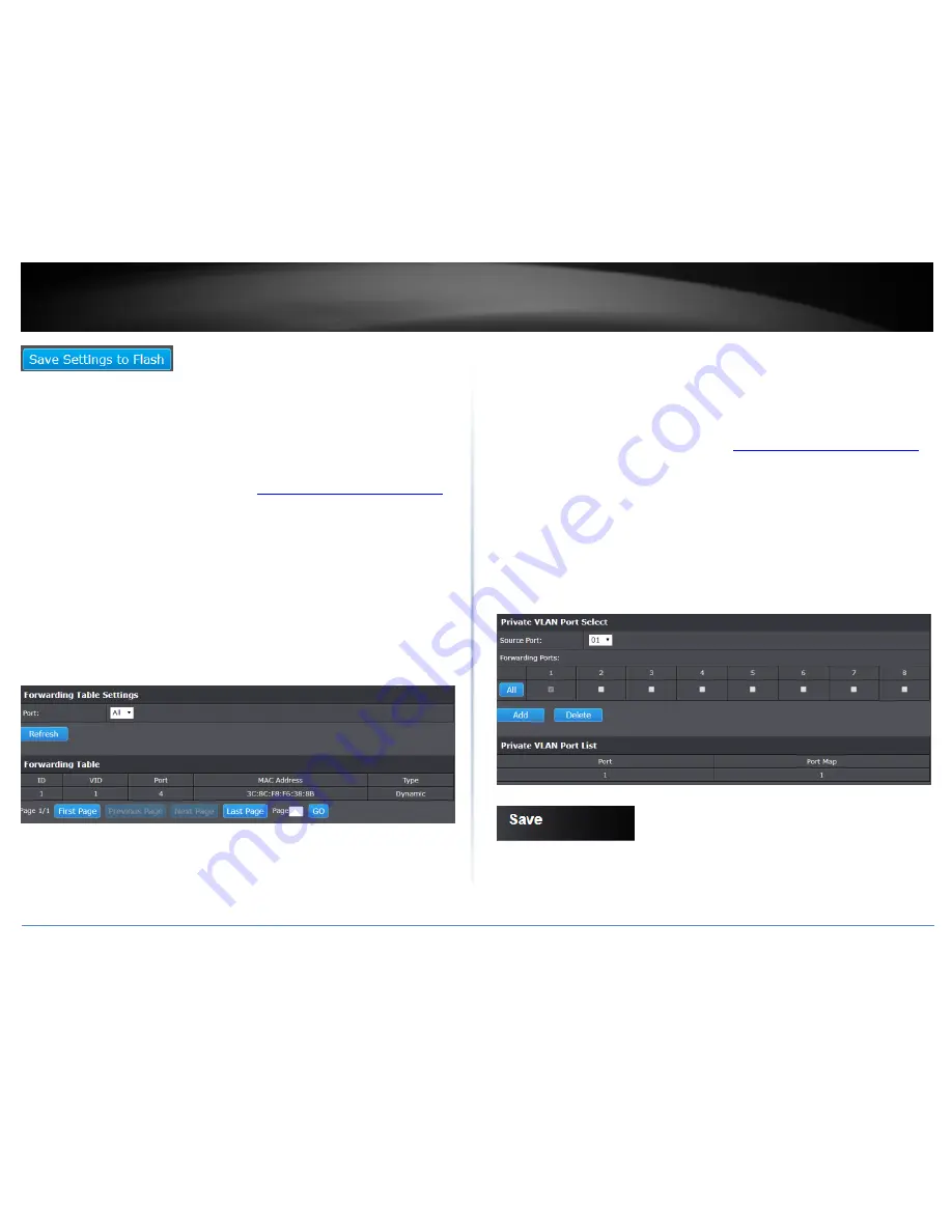
View the switch VLAN Dynamic forwarding table 

Network > VLAN > Forwarding Table  

This section allows you to view the VLAN forwarding table with dynamically generated 
forwarding table entries as devices more devices are connected to your switch. 


1. Log into your switch management page (see “

Access your switch management page

” 

on page 6). 


2. Click on 

Network

, click on 

VLAN, 

and click on 

Forwarding Table


3. By default, forwarding entries for all ports are listed. You can click the 

Port 

drop‐

down list to select a specific port to view only the forwarding entries for the selected 
port.  


If the entries span multiple pages, you can navigate page number in the 

Page

 field and 

click 

Go

 or you can click 

First, Previous, Next, 

and 

Last Page

 to navigate the pages. 


Create a private VLAN 

Network > VLAN > Private 

The private VLAN feature allows you to create a more secure VLAN that is completely 
isolated to its members and cannot communicate with other VLANs 


1. Log into your switch management page (see “

Access your switch management page

” 

on page 6). 


2. Click on 

Network

, click on 

VLAN, 

and click on 

Private


3. To configure Private VLAN Settings, perform the following procedure: 


Select the 

Source Port 

to one of the following choices from the pull‐down 

menu: All, 01 – 08 


Click on the 

Forwarding Ports

 ratio button that applies to your configuration. 


Click 

Add. 


4. In the left hand panel, click on 

Save 


5. Click 

Save Settings to Flash

, then click 

OK


Note: 

This step saves all configuration changes to the NV‐RAM to ensure that if the 

switch is rebooted or power cycled, the configuration changes will still be applied.


Summary of Contents for TPE-TG82ES

Page 1: ...TRENDnet User s Guide Cover Page ...

Page 2: ...n 20 Add static unicast entries to the switch 21 Add static multicast entries to the switch 22 Configure IGMP Snooping Settings 23 Configure IGMP Snooping Group Settings 23 Configure Storm Control 24 Set Ingress Rate Limiting 24 Set Egress Rate Limiting 25 Add modify and remove VLANs 25 Configure VLAN Port Settings 27 Configure the VLAN forwarding Table 27 View the switch VLAN Dynamic forwarding t...

Page 3: ...t 2018 TRENDnet All Rights Reserved TRENDnet User s Guide Table of Contents ii Discovery List 45 Monitor List 45 Device Setting 46 Main Menu Options 47 Technical Specifications 48 Troubleshooting 50 Appendix 51 ...

Page 4: ...d management interface offers features for traffic control LACP RSTP VLAN QoS and monitoring TRENDnet s TPE TG82ES desktop PoE managed switch provides eight gigabit PoE ports for connecting devices such as wireless access points IP cameras and VoIP handsets Ports Eight gigabit PoE ports provide a 16Gbps switching capacity Compact Design With a compact and lightweight metal housing design this desk...

Page 5: ...k PoE or non PoE devices LED Indicators The desktop PoE managed switch includes LED indicators that convey port status Diagnostic LEDs Power LED On When the Power LED is on the device is receiving power Off When the Power LED is off the power adapter is not connected or the device is not receiving power PoE MAX Power over Ethernet Max On When reaching near the max PoE power budget provided 64W or ...

Page 6: ...rt PoE LEDs 1 8 PoE LED button Mode Top Left LED Green on When the Green LED is on the connected device is receiving power Amber on When the Amber LED lights on the connected PoE device is not receiving power The cause is either insufficient power budget or due to Class PowerLimit restrictions in the PoE configurations Off When the LED is off the respective port is either not connected to a PoE de...

Page 7: ...You may need to modify the static IP address settings of your computer s network adapter to IP address settings within your subnet in order to regain access to the switch 5 In the left hand panel click on Save 6 Click Save Settings to Flash then click OK Note This step saves all configuration changes to the NV RAM to ensure that if the switch is rebooted or power cycled the configuration changes w...

Page 8: ...eck the status of the LED indicators on the front panel of your switch to ensure the physical cable connection from your computer or device You can use the Gigabit Ethernet ports as network uplinks Note If you encounter issues connecting to your network there may be a problem with your computer or device network settings Please ensure that your computer or device network settings also called TCP I...

Page 9: ...e User Name and Password are case sensitive Switch Info View your switch status information Switch Info You may want to check the general system information of your switch such as firmware version boot loader information and system uptime Other information includes administration information System MAC Address IPv4 Information and Automatic Network Features information 1 Log into your switch manag...

Page 10: ...Contact Displays the identifying system contact or system administrator of your switch This information can be modified under the System section System MAC Address IPv4 Information MAC Address Displays the switch system MAC address IP Address Displays the current IPv4 address assigned to your switch Subnet Mask Displays the current IPv4 subnet mask assigned to your switch Default Gateway Displays ...

Page 11: ...the settings When you have completed making changes click Apply to save the settings System Name Specifies a name for the switch the name is optional and may contain up to 15 characters System Location Specifies the location of the switch The location is optional and may contain up to 30 characters System Contact Specifies the name of the network administrator responsible for managing the switch T...

Page 12: ...plays the switch MAC address information System IP Address Enter the new switch IP address e g 192 168 200 200 System Subnet Mask Enter the new switch subnet mask e g 255 255 255 0 System Default Gateway Enter the default gateway IP address e g 192 168 200 1 or typically your router gateway to the Internet System IP Mode Click the drop down list and select Static to manually specify your IP addres...

Page 13: ...e new password and enter the new password again the Confirm Password field to verify Then click Apply Note The password consists of up to 12 alphanumeric characters To create additional administrative user accounts Old Password Enter the old password New Password Enter the new password you wish to change it to Confirm Password Enter the password again to confirm the change Note The password consis...

Page 14: ...ow to configure SNMP A Group Name IP address of the switch and at least one community string is the minimum required to manage the switch using SNMP Note If you disable the SNMP on the switch the switch will not be manageable via SNMP using MIBs 1 Log into your switch management page see Access your switch management page on page 6 2 Click on System click on SNMP and click on Global Settings 3 Rev...

Page 15: ...ork managers to define the SNMP Community Name and the access right 1 Log into your switch management page see Access your switch management page on page 6 2 Click on System click on SNMP and click on Community Table Settings 3 Review the settings Click Apply to save the settings Access Right Assign users the level of access from the drop down menu Community Nsme Input the name of this SNMP commun...

Page 16: ...t table entry Enter the Host IP Address for the management device that is to receive the SNMP traps Select the SNMP Version either v1 or v2c that is configured for the host management device Enter a Community Name that you have defined previously in the SNMP Community table The Community Name must correlate with one of the communities displayed on the SNMP Community Table page If you enter a Commu...

Page 17: ...ecific Traffic information Refresh Click the Refresh button to update table with newest traffic information Enable IEEE 802 3az Power Saving Mode System IEEE 802 3az EEE The IEEE 802 3 EEE standard defines mechanisms and protocols intended to reduce the energy consumption of network links during periods of low utilization by transitioning interfaces into a low power state without interrupting the ...

Page 18: ...ates the port is not able to send and receive Ethernet frames Mode This parameter indicates the speed and duplex mode settings for the port You can use this parameter to set the speed and duplex mode of a port The possible settings are o Auto This parameter indicates the port is using Auto Negotiation to set the operating speed and duplex mode The actual operating speed and duplex mode of the port...

Page 19: ...ork can cause bridges to forward traffic indefinitely resulting in increased traffic and reducing network efficiency 1 Log into your switch management page see Access your switch management page on page 6 2 Click on Network click on Spanning Tree and click on Protocol 3 Review the settings Click Apply to save changes Spanning Tree State Select the STP state on the device The possible field values ...

Page 20: ...ew the settings For each entry click Apply to save changes Port Indicates the port number 1 8 Port Fast Select the spanning tree protocol for each port o Network Automatically lets the device determine the type of device that is connected to the port o Disable Disable port fast on a particular port o Edge Indicates that this port is connected to an Edge device 4 In the left hand panel click on Sav...

Page 21: ...necting the cables prior to configuring the ports can create loops in your network topology Loops can result in broadcast storms which can severely limited the effective bandwidth of your network 1 Log into your switch management page see Access your switch management page on page 6 2 Click on Network and click on Trunk 3 Select Enable from the drop down menu under LACP Global Settings 3 Review th...

Page 22: ...down and list and select the port to send the copied ingress egress packets data e g Computer or device with packet capture or data analysis program Frame Type Click the drop down menu and select one of the following options o Ingress This parameter allows configuration of the inbound traffic to the selected port o Egress This parameter allows configuration of the outbound traffic to the selected ...

Page 23: ... a port where a loop was previously detected and blocked Click Apply to save changes In the Loopback Detection table select one of the Loopback Detection Status choices from the pull down menu Enabled This selection enables the Loopback Detection feature for each port This state must be enabled along with the Status field at the top of the page before this feature can be active on the selected por...

Page 24: ...ter the MAC address of the device to add Port Member Select the port where the MAC address will reside Click Apply to add the Static Unicast entry to the list In the list you can click Modify to modify an entry or click Delete or delete the entry You can also click Delete All to delete all the entries in the list If the entries span multiple pages you can navigate page number in the Page field and...

Page 25: ...AN ID 1 MAC Address Enter the multicast group MAC address Group Member Check the port s where the MAC address will reside Note You can click All to select all ports Click Apply to add the Static Multicast Group entry to the list In the list you can click Modify to modify an entry or click Delete or delete the entry If the entries span multiple pages you can navigate page number in the Page field a...

Page 26: ...that if the switch is rebooted or power cycled the configuration changes will still be applied Configure IGMP Snooping Group Settings Network IGMP Snooping Group Settings 1 Log into your switch management page see Access your switch management page on page 6 2 Click on Network click on IGMP Snooping and click on Group Settings 3 Review the settings and click Add to save the settings 802 1Q VLAN In...

Page 27: ...gs to Flash then click OK Note This step saves all configuration changes to the NV RAM to ensure that if the switch is rebooted or power cycled the configuration changes will still be applied Set Ingress Rate Limiting Network Bandwidth Control Ingress Rate Limiting This section allows you to set the ingress receive rate for each switch port 1 Log into your switch management page see Access your sw...

Page 28: ... changes will still be applied Add modify and remove VLANs Network VLAN Tagged VLAN A VLAN is a group of ports that can be anywhere in the network but communicate as though they were in the same area VLANs can be easily organized to reflect department groups such as R D Marketing usage groups such as e mail or multicast groups multimedia applications such as video conferencing and therefore help t...

Page 29: ... these device can be enabled to be VLAN aware Select the tagged VLAN ports to add to the new VLAN Untagged VLAN ports are used to connect edge devices VLAN unaware such as computers laptops and printers to a specified VLAN It is required to modify the Port VID settings accordingly for untagged VLAN ports under Bridge VLAN Port Settings e g If the VID for the VLAN is 2 the PVID should also be set t...

Page 30: ...symmetric VLAN allows the configuration of overlapping untagged VLAN ports in order to create VLAN groups It is recommended to use the standard 802 1Q VLAN mode when possible IVL Independent VLAN Learning SVL Shared VLAN Learning also known as asymmetric VLAN Please note the following when switching between forwarding table modes FDB Forwarding Database will be cleared Static Unicast Address entri...

Page 31: ...age field and click Go or you can click First Previous Next and Last Page to navigate the pages Create a private VLAN Network VLAN Private The private VLAN feature allows you to create a more secure VLAN that is completely isolated to its members and cannot communicate with other VLANs 1 Log into your switch management page see Access your switch management page on page 6 2 Click on Network click ...

Page 32: ... Copyright 2018 TRENDnet All Rights Reserved TRENDnet User s Guide TPE TG82ES 29 ...

Page 33: ...red into the configuration However it is possible that you can find more than one OUI from the same manufacturer among the IP phones you are installing It is also possible that your IP phones are from two or more different manufacturers in which case you will find different OUIs for each manufacturer If you identify more than one OUI among the IP phones being installed then one MAC address represe...

Page 34: ...obal Settings section become active and are eligible for data to be entered o Disable The voice VLAN feature is inactive The other parameter fields in the voice VLAN Global Settings section become inactive and are greyed out so that data cannot be entered In the Voice VLAN Global Settings section enter the configuration information for the following parameters o VLAN ID This parameter is the tagge...

Page 35: ...yed in the table at the bottom of the page Note If you find more than one OUI among the IP phones you are installing enter one MAC address that represents each individual OUI You can enter a total of 10 OUIs Modify OUI Setting To modify or delete an OUI it must be first be deleted and then re created Delete OUI Setting To delete a specific OUI that had already been entered in the table at the bott...

Page 36: ... the switch ports give higher priority to some packets such as delay sensitive traffic over other packets This is referred to as prioritizing traffic Set CoS priority settings QoS CoS 1 Log into your switch management page see Access your switch management page on page 6 2 Click on QoS and click on CoS 3 In QoS Status select Enabled and then click Apply 4 In the left hand panel click on Save 5 Cli...

Page 37: ...SCP values perform the following procedure 1 Log into your switch management page see Access your switch management page on page 6 2 Click on QoS and click on DSCP 3 For each DSCP In value that is relevant to your configuration select a queue Low Medium High or Highest in the Queue column Select Enabled in the DSCP Mapping drop down list Click Apply to save the settings 4 In the left hand panel cl...

Page 38: ...ueues WRR Weighted RoundRobin The port transmits a set number of packets from each queue in a round robin fashion so that each has a chance to transmit traffic 4 In the left hand panel click on Save 5 Click Save Settings to Flash then click OK Note This step saves all configuration changes to the NV RAM to ensure that if the switch is rebooted or power cycled the configuration changes will still b...

Page 39: ... 4W 6 49W to 12 95W 4 34 2W 25 5W to 38 9W Power Budget Power budget is the maximum amount of power that the PoE switch can provide at one time to the connected PDs Port Prioritization As long as the total power requirements of the PDs is less than the total available power of the switch it can supply power to all of the PDs However when the PD power requirements exceed the total available power t...

Page 40: ...his step saves all configuration changes to the NV RAM to ensure that if the switch is rebooted or power cycled the configuration changes will still be applied Configure PoE settings PoE PoE Configuration 1 Log into your switch management page see Access your switch management page on page 6 2 Click on PoE and click on PoE Configuration 3 Review the settings for each port Next to each port entry c...

Page 41: ...e port Note Doing so may damage the device connected to the devices ports Power W Indicates the Power in watts that the port is supplying power to the PD Voltage V Indicates the Voltage in volts as measured at the port when the port is supplying power to the PD Current mA Indicates the Current in milliamps that the port is supplying to the PD 4 In the left hand panel click on Save 5 Click Save Set...

Page 42: ...ng 1 If a firmware upgrade is available download the firmware to your computer 2 Unzip the file to a folder on your computer Please note the following Do not interrupt the firmware upgrade process Do not turn off the device or press the Reset button during the upgrade If you are upgrade the firmware using a laptop computer ensure that the laptop is connected to a power source or ensure that the ba...

Page 43: ...Select File depending on your web browser click on Browse or Choose File 4 A separate file navigation window should open 5 Select the switch configuration file to restore and click Restore Default Filename config bin If prompted click Yes or OK 6 Wait for the switch to restore settings Cable Diagnostics Test Tools Diagnostics The switch provides a basic cable diagnostic tool in the GUI for verifyi...

Page 44: ...ing the switch to factory default settings To reboot your switch You may want to reboot your switch if you are encountering difficulties with your switch and have attempted all other troubleshooting Note You may want to save the settings to flash before reboot the switch under Save Settings to Flash menu Save Settings to Flash button If you have not saved your current configuration settings to fla...

Page 45: ...ck on Tools and click on Reboot 3 Click the Reboot Type drop down list and select from one of the following options Factory Default Resets all switch configuration settings to factory defaults including the IP address Factory Default Except IP Resets all switch configuration settings to factory defaults and leaves the current IP address configuration The switch factory default settings are below A...

Page 46: ...ight 2018 TRENDnet All Rights Reserved TRENDnet User s Guide TPE TG82ES 43 4 At the Install Location installation window click Next 5 At the Installation click Install 6 In the Completion window click Finish ...

Page 47: ...tically created Double click the icon to start the utility or open the utility if it is already running Closing the utility will exit the application You can also click Exit at the bottom of the utility user interface to exit the application You can also launch the utility from the Start Menu programs Start Programs or All Programs TRENDnet Management Utility TRENDnet Management Utility exe ...

Page 48: ... Mask Shows the Subnet Mask set of the device Gateway Shows the Gateway set of the device Group Interval Monitor List All the Web Smart switches in the Monitor List can be monitored you can also receive the trap and show the status of the device System word definitions in the Monitor List S Shows the system symbol of the Web Smart device represent for device system is not alive IP Address Shows th...

Page 49: ...ocess the data change immediately The default password of TRENDnet Web Smart Switches is admin Password Change You can use this Password Change when you need to change the password fill in the password needed in the dialog box and press Set button to proceed the password change immediately Firmware Upgrade When the device has a new function there will be a new firmware to update the device use thi...

Page 50: ...Load To manually load the setting file of the Monitor List Exit To exit the Web Management Utility In the View TAB there are view log and clear log function this function will help you to show trap setting View Log To show the event of the Web Management Utility and the device Clear Log to clear the log In the Option TAB there are Refresh Time and Group Interval Refresh Time This function helps yo...

Page 51: ...ies Jumbo Frames 9KB Forwarding rate 11 9Mpps 64 byte packet size Management HTTP Web based GUI SNMP v1 v2c Cable diagnostic test Backup Restore Configuration Upload Firmware Spanning Tree IEEE 802 1d STP spanning tree protocol IEEE 802 1w RSTP rapid spanning tree protocol Link Aggregation 802 3ad Dynamic LACP up to 2 groups Quality of Service QoS Port based QoS 802 1p Class of Service CoS Bandwid...

Page 52: ...50 60Hz 1 2A Output 54V DC 1 67A external power adapter Max consumption 68 6W PoE PoE budget 64W 802 3at Up to 30W per port PoE Mode A Pins 1 2 for power and pins 3 6 for power PD auto classification Over current short circuit protection Fan Acoustics Fanless design MTBF 730 455 hours Operating Temperature 0 40 C 32 104 F Operating Humidity Max 90 non condensing Dimensions 171 x 97 8 x 28 6mm 6 73...

Page 53: ...ction icon and click Properties c Click Internet Protocol Version TCP IPv4 and then click Properties d Then click Use the following IP address and make sure to assign your network adapter an IP address in the subnet of 192 168 10 x Click OK Windows XP 2000 a Go into the Control Panel double click the Network Connections icon b Right click the Local Area Connection icon and the click Properties c C...

Page 54: ...us and your IP address settings displayed Note If you are experiencing difficulties please contact your computer or operating system manufacturer for assistance How to configure your network settings to use a static IP address Note Please note that although the following procedures provided to follow for your operating system on configuring your network settings can be used as general guidelines h...

Page 55: ... static IP address Then click the Apply button f Restart your computer Note If you are experiencing difficulties please contact your computer or operating system manufacturer for assistance How to find your MAC address In Windows 2000 XP Vista 7 8 1 10 Your computer MAC addresses are also displayed in this window however you can type getmac v to display the MAC addresses only In MAC OS 10 4 1 Appl...

Page 56: ...na Increase the separation between the equipment and receiver Connect the equipment into an outlet on a circuit different from that to which the receiver is connected Consult the dealer or an experienced radio TV technician for help WARNING Any changes or modifications to this product not expressly approved by the party responsible for compliance could void the user s authority to operate the equi...

Page 57: ...lace the defective product or there is no comparable model available we will refund the depreciated value of the product If a product does not operate as warranted during the applicable warranty period TRENDnet shall reserve the right at its expense to repair or replace the defective product or part and deliver an equivalent product or part to the customer The repair replacement unit s warranty co...

Page 58: ...SE NEGLECT IMPROPER INSTALLATION OR TESTING UNAUTHORIZED ATTEMPTS TO REPAIR OR MODIFY OR ANY OTHER CAUSE BEYOND THE RANGE OF THE INTENDED USE OR BY ACCIDENT FIRE LIGHTNING OR OTHER HAZARD LIMITATION OF LIABILITY TO THE FULL EXTENT ALLOWED BY LAW TRENDNET ALSO EXCLUDES FOR ITSELF AND ITS SUPPLIERS ANY LIABILITY WHETHER BASED IN CONTRACT OR TORT INCLUDING NEGLIGENCE FOR INCIDENTAL CONSEQUENTIAL INDI...

Page 59: ......

Reviews: