22
NOTE
Run input power, motor wiring and control
wiring in three separate metallic conduits or
raceways for high frequency noise isolation.
Failure to isolate power, motor and control
wiring could result in less than optimum drive
and associated equipment performance.
Electrical Installation, Control Wiring
Torque: 5 - 6 in-lbs
Screw size: M3
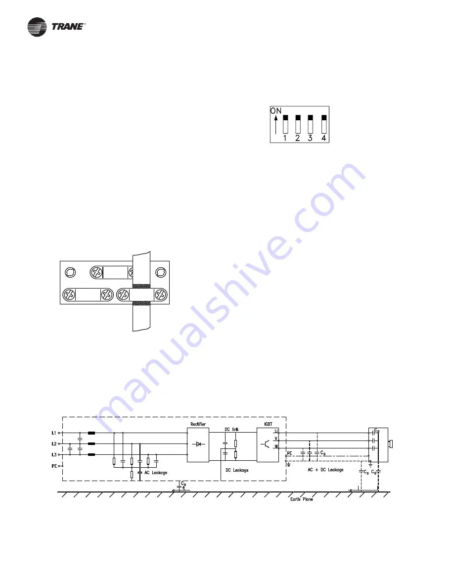
Shielded control wires are recommended. To reduce interference from
electrical noise, ground the cable shield at a cable clamp, as shown
below, at both ends. Connect the shield to the grounded clamp. Very
long control wires may create 60 Hz interference. To resolve this,
connect one end of the shield to earth with a 0.1
µ
F capacitor, keeping
the leads as short as possible. If interference persists, disconnect the
grounded shield connection at the end opposite to the drive.
DIP Switches 1 through 4
DIP switches are located on the control card.
They are used for serial communication and the common of digital
inputs 16 through 33. The switch positions shown are the factory
settings.
Switch 1 is not used.
Switches 2 and 3 are used for terminating serial communication. On the
first and last drive in a multiple device network, or on the only drive of a
single drive network, switches 2 and 3 must be ON (the default setting).
On all other drives in a multiple device network, set switches 2 and 3 to
OFF.
Switch 4 separates the common for the internal 24 VDC supply from the
common of the external 24 VDC supply. Normally this switch is ON and
the power supply is present at terminals 12 and 13. Set Switch 4 to the
OFF position when an external 24 VDC supply is used.
Ground Leakage Current
It is normal for there to be some leakage current from the drive to earth
ground. Paths of current leakage are shown on the drawing below.
The leakage current will exceed 3.5 mA.
Paths of Normal Current Leakage to Ground


