background image

General Information

8

 AFDE-SVU02F-EN

Note:

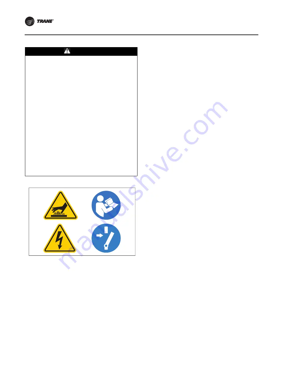
Graphic labels (shown above) are used for CE 
application only.

Important:

Before servicing, disconnect all power sources and 
allow at least 10 minutes for capacitors to discharge.

All electrical enclosures—unit or remote—are IP2X.

WARNING

Hazardous Voltage w/Capacitors!

Failure to disconnect power and discharge capacitors 
before servicing could result in death or serious injury. 
Disconnect all electric power, including remote 
disconnects and discharge all motor start/run 
capacitors before servicing. Follow proper lockout/
tagout procedures to ensure the power cannot be 
inadvertently energized. For variable frequency drives 
or other energy storing components provided by Trane 
or others, refer to the appropriate manufacturer’s 
literature for allowable waiting periods for discharge of 
capacitors. Verify with an appropriate voltmeter that all 
capacitors have discharged.

Before working on the controller, check to be sure 
capacitors are discharged with a DC voltmeter on the 
1000V scale. Charged capacitors require at least 
10 minutes to discharge to less than 50Vdc after line 
power is removed.

Before proceeding with the startup procedure, 
disconnect and lockout all incoming power to the 
drive controller!

For additional information regarding the safe discharge 
of capacitors, see PROD-SVB06*-EN.

X39003893001A

Summary of Contents for Liquid-Cooled Adaptive Frequency AFDE

Page 1: ...e equipment The installation starting up and servicing of heating ventilating and air conditioning equipment can be hazardous and requires specific knowledge and training Improperly installed adjusted or altered equipment by an unqualified person could result in death or serious injury When working on the equipment observe all precautions in the literature and on the tags stickers and labels that ...

Page 2: ...or handling reclaiming recovering and recycling of certain refrigerants and the equipment that is used in these service procedures In addition some states or municipalities may have additional requirements that must also be adhered to for responsible management of refrigerants Know the applicable laws and follow them Note Graphic labels shown above are used for CE application only Important Before...

Page 3: ...oves safety glasses hard hat bump cap fall protection electrical PPE and arc flash clothing ALWAYS refer to appropriate Safety Data Sheets SDS and OSHA guidelines for proper PPE When working with or around hazardous chemicals ALWAYSrefertotheappropriateSDSandOSHA GHS Global Harmonized System of Classification and Labeling of Chemicals guidelines for information on allowable personal exposure level...

Page 4: ...wer and Control Wiring 31 Installing Input Power Wiring Standard Cabi net 31 Installing External 120 Vac Control Power 32 Torquing Electrical Power Connections 32 Cabinet Wire Routing 32 Wire Routing 32 Wire Sizing 32 Grounding the Cabinet 33 AFDE Cooling Circuit 35 Liquid Cooling Connections 36 Factory Connected on Unit Mounted Drives 36 UC800 AFD Operation 38 Adaptive Frequency Drive Control 38 ...

Page 5: ... a qualified service organization Note Graphic labels shown above are used for CE application only Important Before servicing disconnect all power sources and allow at least 10 minutes for capacitors to discharge All electrical enclosures unit or remote are IP2X NOTICE Do Not Megohm Test Failure to follow instructions below could cause damage to the controller circuitry Do NOT use a megger to perf...

Page 6: ...ss 9 Check to assure incoming power to the drive is phased A B C AFDE Checks WARNING Capacitors Must Be Allowed To Discharge Failure to disconnect power and discharge capacitors before servicing could result in death or serious injury Each time power is removed allow at least 10 minutes for DC units to discharge after power is disconnected before servicing Use extreme caution when applying power E...

Page 7: ... bypassed for servicing use extreme caution when performing the startup X39003893001A WARNING Proper Field Wiring and Grounding Required Failure to follow code could result in death or serious injury All field wiring MUST be performed by qualified personnel Improperly installed and grounded field wiring poses FIRE and ELECTROCUTION hazards To avoid these hazards you MUST follow requirements for fi...

Page 8: ...edures to ensure the power cannot be inadvertently energized For variable frequency drives or other energy storing components provided by Trane or others refer to the appropriate manufacturer s literature for allowable waiting periods for discharge of capacitors Verify with an appropriate voltmeter that all capacitors have discharged Before working on the controller check to be sure capacitors are...

Page 9: ...ould result in death or serious injury Technicians in order to protect themselves from potential electrical mechanical and chemical hazards MUST follow precautions in this manual and on the tags stickers and labels as well as the following instructions Unless specified otherwise disconnect all electrical power including remote disconnect and discharge all energy storing devices such as capacitors ...

Page 10: ...quipment is interlocked with other equipment 115 volts AC may be present in the cabinet even though the main power is disconnected If this is the case these interlock signals should be deactivated before any work is performed on this equipment Suitable warning tags or disconnects should be added to these circuits and all circuits should be tested before attempting to energize or service the contro...

Page 11: ... and into a section of capacitors that are used to store the DC voltage TheDCoutputfeedstheinverterIGBTsthatswitch at predetermined time to change the DC input voltage to a symmetrical AC output voltage of desired magnitude and frequency The output frequency range is 38 to 60 hertz The DC voltage is fixed at 700 Vdc A variable output is accomplished by PWM control within the inverter by the IGBTs ...

Page 12: ...or Change J0 Chill Plate Redesign K0 Addition of Common Mode Magnetic Core Choke Mounting Brackets L0 Updated Circuit Breaker and Control Power Transformer M0 Added Line Voltage Digit N0 Touch Safe Control Circuit Fuse Blocks P0 Pre Charge Contactor Reduction and Back Plate Modification R0 New Precharge Contactor T0 External 120 Vac hookup binding from keypad Digit 12 AFD Mounting Location A Unit ...

Page 13: ...ne AFDE cabinets have the following main components For convenience the drive is discussed in two sections a rectifier input and inverter output sections See Figure 1 p 15 and Figure 3 p 18 for Frame 3 and Figure 4 p 19 Figure 5 p 21 and Figure 7 p 24 for Frame 4 Drive Cabinet Component Locations Frame 3 Units 179910 903 and 179910 905 The main drive components for a Frame 3 unit are listed below ...

Page 14: ...3 Line Sync PCB Assembly 24 Line Sync PCB Cover 25 Terminal Block Fans 6 Position 26 Surge Suppressor 27 OIM Note OIM is mounted inside panel for design sequence P0 and earlier OIM is mounted outside panel for design sequence R0 and later ...

Page 15: ...ve and Cabinet AFDE SVU02F EN 15 Figure 1 Drive components locations Frame 3 units L1 L2 W V U L1 L3 L2 L3 12 User Supplied Motor Leads 21 5 13 25 19 10 1 2 11 26 9 14 20 3 4 15 16 17 6 7 8 23 24 22 18 27 ...

Page 16: ...Drive and Cabinet 16 AFDE SVU02F EN Figure 2 Magnetic choke 27 Note Cores are only used when compressor has steel bearings AFD Enclosure ...

Page 17: ...h Flex Film 7 Wire Harness Assembly Power Supply Upper Gate 8 Inverter Power Interface Assembly 9 Wire Harness Assembly Power Supply Lower Gate 10 Insulation Sheet 11 DPI Communications Interface 12 Rectifier Power Interface Assembly 13 Wire Harness Assembly Gate Driver 14 Wire Harness Assembly Current Feedback Device 15 Wire Harness Assembly Line Sync 16 Wire Harness Assembly DC Bus Bleeder Resis...

Page 18: ...Drive and Cabinet 18 AFDE SVU02F EN Figure 3 Power module component locations door open Frame 3 units 16 13 2 14 12 8 10 4 4 10 3 7 7 1 1 9 9 11 6 5 6 5 7 25 ...

Page 19: ...Drive and Cabinet AFDE SVU02F EN 19 Figure 4 Power module component locations door closed Frame 3 units 22 21 23 20 11 19 17 18 24 20 25 ...

Page 20: ...lier OIM is mounted outside panel for design sequence R0 and later 7 Fans 115Vac Inductor 4 8 Transformer 115Vac Control Power 9 Fan 115Vac Contactor 10 Resistors 100k Ohms 50W 11 Precharge Resistors 12 Relay Oil Pump and Control Power Terminals 13 Fuse Class J 600V 10A 2 14 Fuse Class J 600V 25A 1 15 Fuse Class CC 600V 10A 1 16 Fuse Class T 600V 300A 3 17 Fuse Class CC 600V 20A 3 18 Fuse Class CC...

Page 21: ...SVU02F EN 21 Note Units with CE certification include touch safe barriers not shown Figure 5 Drive component locations Frame 4 units L1 L2 L3 L1 L2 L3 U V W 11 17 3 9 2 19 23 16 1 10 22 8 13 14 24 15 25 5 21 7 6 21 18 4 12 20 ...

Page 22: ...Drive and Cabinet 22 AFDE SVU02F EN Figure 6 Magnetic choke Note Cores are only used when compressor has steel bearings AFD Enclosure ...

Page 23: ...ernal Fan 24Vdc 5 Wire Harness Assembly Internal Fan 6 Wire Harness Assembly DC Power 7 Wire Harness Assembly DC Bus Resistors under top cover 8 Current Feedback Device 2000 A 9 Wire Harness Assembly Current Feedback Device Rectifier Side 10 Wire Harness Assembly Current Feedback Device Inverter Side 11 Wire Harness Assembly RTD Recitifier Side 12 Wire Harness Assembly RTD Inverter Side 13 Cable A...

Page 24: ...Drive and Cabinet 24 AFDE SVU02F EN Figure 7 Power module component locations IO and control panel removed Frame 4 units 5 3 1 2 9 11 8 12 4 10 6X 9 6 2X 7 ...

Page 25: ...Drive and Cabinet AFDE SVU02F EN 25 Figure 8 Power module component locations front panel removed Frame 4 units 18 13 16 17 14 15 2X ...

Page 26: ...Figure 10 p 27 shows overall dimensions for Frame 4 units Figure 9 Drive cabinet dimensions Frame 3 in mm 11 88 301 6 17 21 437 1 14 12 358 8 27 45 697 1 8 24 209 3 29 50 749 3 24 00 609 6 60 00 1524 2 38 60 5 10 00 254 3 25 82 6 18 00 457 2 3 50 88 9 2 313 58 7 69 00 1752 6 3 50 88 9 62 00 1574 8 24 00 609 6 Input Wiring Panel 10 6 x 15 3 269 2 x 388 6 Opening with cover removed 0 563 W x 1 563 L...

Page 27: ...VOLTAGE BACK OF CHILL PLATES RIGHT END VIEW INPUT WIRING PANEL OPENING COVER REMOVED TOP VIEW 15 00 OPENING 2 75 69 9 2 98 75 7 19 25 489 0 15 00 381 8 02 203 7 6X 1 38 35 1 33 0 838 2 5 00 127 0 70 36 1787 1 75 11 1907 5 4 57 116 1 8 43 214 1 67 77 1721 4 97 79 2483 9 26 00 660 4 23 00 584 2 8 10 205 7 2 38 60 5 2 93 74 4 2 61 66 3 25 00 635 ...

Page 28: ... is performed on this equipment Suitable warning tags or disconnects should be added to these circuits and all circuits should be tested before attempting to energize or service the controller For additional information regarding the safe discharge of capacitors see PROD SVB06 EN WARNING Refrigerant Vapor Hazard Failure to follow instructions could result in death or serious injury Recover refrige...

Page 29: ...ecessary to cut and remove the mounting brackets below the drive it is recommended that alignment or fish plates be field constructed to assure the brackets are properly re aligned when they are reinstalled Re assembly of the drive is essentially the reverse of the aboveprocedure Thedriveenclosuretomountingbracket bolts should be torqued to 90 ft lb 122 N m The drive enclosure to motor terminal tr...

Page 30: ...qued to 70 ft lb 94 9 N m Refrigerant line flanges with 5 16 in 0 8 cm bolts must be torqued to 17 ft lb 23 0 N m The FLEXIBAR flexible insulated busbar connections to the motor terminals should be torqued to 27 ft lb 36 6 N m Frame 3 drives 608 Amp and 405 Amp have an orifice plate located between the inlet flange and the heat sink The orifice plate sits between two gaskets Frame 4 drives have no...

Page 31: ... 10 6 8 10 6 16 4 25 2 or 1 35 1 0 50 2 0 70 2 0 or 3 0 95 4 0 or 250 120 300 150 350 or 400 185 450 or 500 240 Note AWG American Wire Gauge WARNING Hazardous Voltage w Capacitors Failure to disconnect power and discharge capacitors before servicing could result in death or serious injury Disconnect all electric power including remote disconnects and discharge all motor start run capacitors before...

Page 32: ...rical joint will be low carbon steel The hardware does not carry electrical current but holds the two conducting surfaces together under pressure When properly torqued the slight elongation of the bolt or screw acts to maintain pressure on the electrical joint The thermal expansion of steel is less than that of the conducting metals which is usually copper The pressure at the electrical joint will...

Page 33: ...375 in lb 42 4 N m WARNING Hazardous Voltage Improper Grounding Hazardous voltage due to improperly grounded electrical components could result in death or serious injury The motor controller has a chassis ground that must be connected to an earth ground X39003893001A Table 4 Standard wiring requirements AFD control wiring between the chiller and the starter AFD Starter to Control Panel Control Wi...

Page 34: ...h is 65 000 amps at 480 Vac WARNING Proper Field Wiring and Grounding Required Failure to follow code could result in death or serious injury All field wiring MUST be performed by qualified personnel Improperly installed and grounded field wiring poses FIRE and ELECTROCUTION hazards To avoid these hazards you MUST follow requirements for field wiring installation and grounding as described in NEC ...

Page 35: ...which then flows to the condenser Frame 3 405A 608A utilizes a single chill plate A small orifice is installed in the lower flange inlet at the drive The purpose of the orifice is to regulate the amount of refrigerant that enters the drive Frame 4 900A 1210A utilizes dual chill plates No orifices are used on the lower flange inlets The differential pressure across the refrigerant pump is normally ...

Page 36: ...erants refrigerant substitutes or refrigerant additives Failure to follow proper procedures or the use of non approved refrigerants refrigerant substitutes or refrigerant additives could result in death or serious injury or equipment damage Figure 14 Coolant lines Outlet Outlet Torque to 70 ft lb 94 9 N m 1 1 8 in 2 9 cm OD Torque to 70 ft lb 94 9 N m 1 1 8 in 2 9 cm OD Inlet Inlet Torque to 17 ft...

Page 37: ...d excessive nicks 2 On both the inlet and outlet connections place a new flange gasket over the studs on the back side of the drive 3 Align the chiller tubing and flanges over the studs on the drive so that the flanges are straight and parallel Place the proper washers and nuts over the studs and snug them up by hand Be careful to maintain the parallel alignment of the flanges 4 Use a socket and t...

Page 38: ...ptimal operating condition is found the algorithm can avoid the surge in the future When surge is detected a surge recovery routine makes adjustments to move out of surge reestablish stabile operating conditions and adjust the control boundary to avoid surge in the future Chiller and AFD Sequence of Operation In the UC800 the chiller AFD sequence of operation is identical to a standard fixed speed...

Page 39: ... Startup The starting speed for AFD under UC800 control will vary depending upon the pressure ratio acrossthe compressor For most starts the pressure ratio will be small and the AFD will start at its minimum speed The speed will be adjusted every 5 seconds in response to changing pressure ratio and load requirements On startup shell pressures and temperatures may not correspond to saturated condit...

Page 40: ...ion with the IGV position at the end of the last re optimization time and if greater than the user adjustable sensitivity will re optimize 3 When the re optimization timer expires The control is re optimized by increasing the AF Surge Boundary Offset Coefficient every minute until surge occurs When surge occurs the control will go into surge recovery until the surge flag is removed and all of the ...

Page 41: ...ction Surge detection control logic monitors changes in compressor motor current A surge occurrence leaves a characteristic motor current signature as shown in Figure 18 This signature is formed because the transitory pressure breakdown between the condenser and evaporator causes a sudden reduction in compressor motor load As the pressures equalize the compressor begins to quickly load increasing ...

Page 42: ...nd the cooling circulating pump The contacts are Normally Open and closed when the AFD energizes the motor Note Unlike locked rotor amps associated with electromechanical starters the phase currents are not expected to rise above 85 percent RLA prior to 1 6 seconds following the sending of the speed signal after which they then remain above 85 percent RLA until the compressor motor has come up to ...

Page 43: ... panel cabinet for easy access TheTracer TU softwareprovidesaccesstothatparticular machine s configuration settings customizable limits status and up to 60 active or historic alarms A technician can interact with an individual device or a group of devices for advanced troubleshooting For more information on Tracer TU visit your local Trane Service company or Trane s website at www Trane com Use Tr...

Page 44: ...optimization If the difference is greater than the AF Re optimization Sensitivity setting re optimization occurs This value is adjustable from 0 to 100 where 0 would guarantee re optimization every 30 minutes and 100 would guarantee no re optimization Table 9 Tracer TU Field Startup view Adjustable Frequency Drive section Description Min Max Factory Default Units Maximum Frequency 38 60 60 Hertz H...

Page 45: ...te Data Flux Current Ref 0 1 200 a Amps Nameplate Data Acceleration Time 1 99 10 Seconds Deceleration Time 1 99 30 Seconds Starter Current Limit 1 3 200 1 1 2XNMRA a Amps Nameplate Data Current Limit Gain 0 5 000 10 Power Loss Mode decel coast decel Power Loss Time 0 25 0 Seconds Default is 0 if you encounter AFD power loss try 5 sec Flying Start 0 disable 1 enable 0 Enabled is not recommended Fly...

Page 46: ...g Unknown lowest priority and displays last Active alarms are followed by any historical alarms These appear gray on the screen The alarms button at the bottom of the screen flashes between two colors depending on the severity of the highest priority alarm i e Immediate shutdownalarms cause the button to flash between red and black and Normal shutdown alarms cause the button to flash between yello...

Page 47: ...shooting a Measure and record the DC bus via the Operator Interface Module OIM b Check ALL wiring tightness ribbon cables fully seated proper phasing etc c Refer to the Rockwell manuals for further troubleshooting information manual D2 3496 1 d If possible Use the Rockwell OIM and provide the following drive parameter information LiquiFlo 2 0 inverter Parameters 49 50 209 210 224 225 226 227 228 2...

Page 48: ... 219 Rctfr IT Overld Motor Short 38 Phase U to Grnd Drive Overcurrent 220 Rctfr 12T Overld Motor Short 39 Phase V to Grnd Power Loss 221 Ride Thru Abort Motor Short 40 Phase W to Grnd High Bus 222 High AC Line Motor Short 41 Phase UV Short Power Loss 223 Low DC Bus Motor Short 42 Phase VW Short High Bus 224 Rctfr Over Volt Motor Short 43 Phase WU Short Power Loss 225 Input I Imbalance General 48 P...

Page 49: ...ure These conditions could cause equipment damage Do not power up equipment if you have concerns regarding equipment condition Upon initial power up remain in the area for the first two hours of operation and observe the chiller and drive for any abnormalities Contact CenTraVac Chiller Technical Support for assistance if needed WARNING Hazardous Voltage Failure to follow the instructions below cou...

Page 50: ... the drive LLID follow the procedure below a The drive s main DC bus must be charged in order for the drive LLID to be recognized or bound Close the drive disconnect and apply line power to the drive b With a laptop connected to the chiller and with Tracer TU running enter the binding view menu of Tracer TU and locate the AFD Starter LLID in the menu Select the Bind button for the AFD Starter LLID...

Page 51: ...ata Motor NP RLA RLA Motor NP Power KW Motor NP Hertz Volts Hz Motor NP PRM Prestart Checks Date Checked Stator Resistance Drive Grounded Flux Current Ref Motor Rotation Acceleration Time 30 Drive Chassis Grounded Deceleration Time 30 Control Wiring Tight Starter Current Limit Drive Connections are Tight Current Limit Gain 10 Verified Settings Power Loss Mode Decel Power Loss Time 0 Comments Flyin...

Page 52: ...or any signs of leakage arcing etc 9 Check ALL cable lug terminal connections inside the drive enclosure Ensure all are clean and tight and not rubbing against each other anywhere 10 Check any bypass or pre charge contactors Confirm the contacts are in serviceable condition and that the contactor operates smoothly 11 Re seat all ribbon cable or control wire plugs to ensure all are snug and tight 1...

Page 53: ...ncy drives for centrifugal chillers equipped with LF 2 0 AFDE starters and Operator Interface Module OIM and special cable are required All UC800 chillers will be equipped with the OIM as standard on the drive power module This is for service only and NEVER for machine operation These items are available from Trane with the following part numbers OIM Operator Interface Module MOD01352 Cable for OI...

Page 54: ...eference an as built schematic wiring diagram and a field wiring connection diagram are located inside the main control panel door of the chiller Figure 21 Field connection diagram CVHE CVHF CVHG Trane supplied Adaptive Frequency Drive 1 of 2 ...

Page 55: ...Figure 22 Field connection diagram CVHE CVHF CVHG Trane supplied Adaptive Frequency Drive 2 of 2 Wiring Schematics AFDE SVU02F EN 55 ...

Page 56: ... ONLY L1 L2 L3 GND 1 L1 3 L2 5 L3 TRANE SUPPLIED REMOTE MOUNTED ROCKWELL MEDIUM VOLTAGE ADAPTIVE FREQUENCY DRIVE SHOWN SEE DETAIL A FOR TRANE SUPPLIED UNIT MOUNTED LOW VOLTAGE ADAPTIVE FREQUENCY DRIVE 1 24V 2 GND 3 COM 4 COM 2K36 AFD COMMUNICATION CARD RED BLK BLU GRY WB4 RED BLK BLU GRY SHIELD 1T2 J5 1 1T2 J5 2 1T2 J5 3 1T2 J5 4 1X1 G WB4 SHIELDING TO BE GROUNDED AT MAIN CONTROL PANEL ONLY DTB1 D...

Page 57: ...2 10VDC OR 4 20mA GENERIC REFRIGERANT MONITOR INPUT 1K6 J2 2 1K6 J2 3 1K6 J2 5 1K6 J2 6 2 10VDC OR 4 20mA EXTERNAL CURRENT LIMIT SETPOINT 2 10VDC OR 4 20mA EXTERNAL CHILLED WATER SETPOINT 1K5 J2 2 1K5 J2 3 1K5 J2 5 1K5 J2 6 2 10VDC RLA COMPRESSOR OUTPUT GENERIC BAS 2 10VDC CONDENSER REFRIGERANT PRESSURE OR EVAPORATOR CONDENSER DIFFERENTIAL PRESSURE OUTPUT OR CONDENSER HEAD PRESSURE CONTROL 1K1 LIN...

Page 58: ......

Page 59: ......

Page 60: ...are committed to using environmentally conscious print practices Trane by Trane Technologies NYSE TT a global climate innovator creates comfortable energy efficient indoor environments for commercial and residential applications For more information please visit trane com or tranetechnologies com AFDE SVNU02F EN 20 Jun 2020 Supersedes AFDE SVU02E EN Mar 2016 ...

Reviews: