


User's Manual l TQMa8XxS UM 0101 l © 2022, TQ-Systems GmbH
Page 23
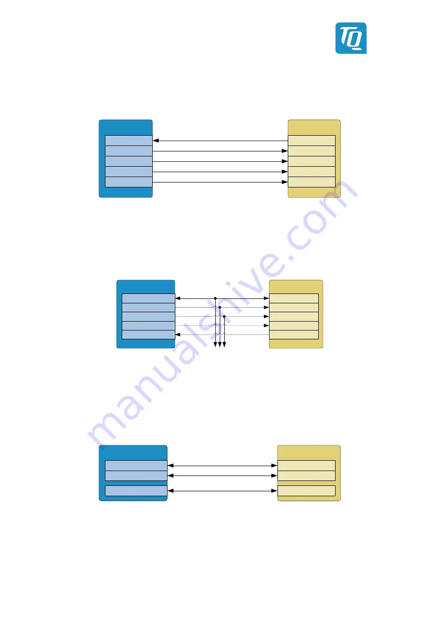
3.3.7
SPI
For the SPI0 interface of the SMARC pins, the SAI0 balls of the i.MX 8X are used. For the provision of the second chip select signal,
however, a SAI1 ball of the CPU is used.
i.MX 8X
SMARC-Pins
SAI0_RXD
SPI0_CK
SPI0_DIN
SPI0_CS0#
SAI0_TXC
SPI0_DO
SAI0_TXD
SAI0_TXFS
SAI1_RXD
SPI0_CS1#
Figure 18: Block diagram SPI
3.3.8
eSPI
The QSPI0B interface of the i.MX 8X is connected to the eSPI pins. The signals are only routed to the outside if the optional NOR
Flash is not assembled. Since this is a memory interface and not an eSPI interface according to Intel standard, functional
restrictions are to be expected if other devices than QSPI memory are connected. The signals ESPI_RESET# and ESPI_ALERT0# are
realized with GPIOs of the CPU. ESPI_ALERT1# is not used.
i.MX 8X
SMARC pins
GPIO
ESPI_CS[1:0]#
ESPI_IO_[3:0]
ESPI_RESET#
QSPI0B_DATA[3:0]
ESPI_CK
QSPI0B_SCLK
QSPI0B_SS[1:0]#
ESPI_ALERT[1:0]#
NOR flash (optional)
GPIO
Figure 19: Block diagram eSPI
3.3.9
Serial ports
Two UART interfaces of the i.MX 8X may be used due to multiplexing. UART0 of the CPU is provided including CTS and RTS
signals at the SER0 pins. The SCU-UART interface of the i.MX 8X is connected to SER1. The UART interfaces can be used by the
software to output boot messages. The SER2 and SER3 interfaces are not used. Instead of SCU_UART also UART3 or M4_UART0
can be multiplexed to these pins.
i.MX 8X
SMARC-Pins
SER1_RX/TX
SER0_RX/TX
UART0_RX/TX
SER0_RTS#/CTS#
FLEXCAN0_RX/TX
SCU_GPIO0_00/01
Figure 20: Block diagram Serial Ports


