❍
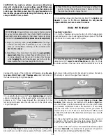
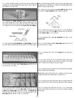
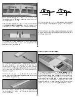
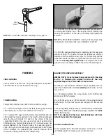
8. Using a 1/4" x 1/4" x 36" balsa stick, make the Center
Stringer. Use medium CA to glue it into position. Using leftovers
saved from the assembly of the Fin and Stab, cut the center
supports and glue them into position. Position the center supports
as accurately as possible, as the installation of the formers as well
as the top and bottom of the fuse depends on their locations.
❍
9. Once the glue sets, remove the Fuselage Side from your
building surface. Examine and add thick CA glue to any open joints,
then use your sanding block or bar sander with medium (150-grit)
sandpaper to sand both sides of the Fuselage Side smooth.
❍
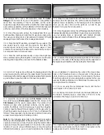
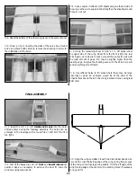
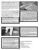
10. Place the Right Fuse Side underneath the wax paper. (The
side doesn’t have to align with the plans for this step.) The
doubler should be facing away from the wax paper or plan
protector. The remaining Fuse Side will be built directly on top of
our completed side to insure accuracy.
❍
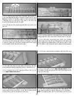
11. Place the Left Fuse Side directly on top of the Right Fuse
Side, carefully aligning them together. Use T-pins to lock the two
sides together. Repeat the procedure for the Stabilizer Base.
❍
12. Make the Fuse Rails for the Left Fuse Side using the same
technique from the right side. The Left Fuse Side must match the
Right as closely as possible, or the fuselage will not be straight
when you are done. Once all the parts are cut and fit, use
Medium CA to glue them into position.
❍
13. Once the glue sets, remove the Left Fuselage Side from the Right
Fuselage Side. Examine and add thick CA glue to any open joints, then
use your sanding block or bar sander with medium (150-grit)
sandpaper to sand both sides of the Left Fuselage Side smooth.
❍
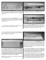
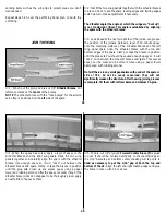
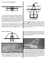
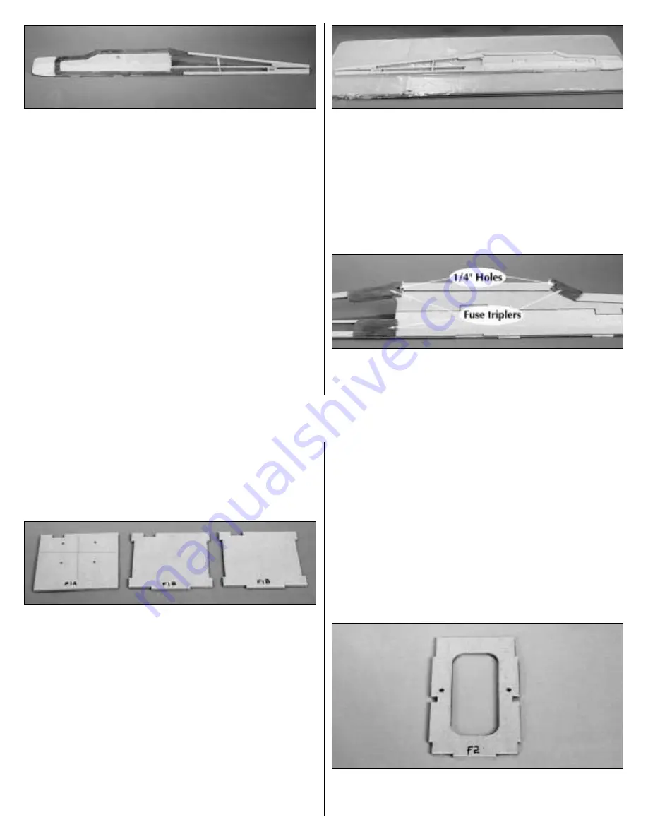
14. Locate the three fuselage triplers and glue them in their proper
locations on the inside of the fuselage. Make sure the alignment of
the triplers doesn’t interfere with the notches for the formers.
15
❍
15. Drill 1/4" holes as shown through the fuselage sides for the
wing dowels using the notches in the upper triplers for alignment.
Carefully sand the bottom edges of the fuselage sides flat to provide
a good surface to glue the bottom of the fuse into position.
Fuse Structure Assembly
❍
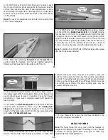
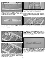
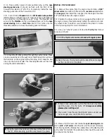
1. Locate the die-cut 1/8" plywood F1A Former and the two
die-cut 1/8" plywood F1B Formers. Center the F1A Former on the
F1B Formers with the punch marks visible. The notches of all
formers will align when positioned correctly. Use the plans to
position the formers. Use 30-minute epoxy to glue them together.
Clamp or tape the firewall formers together until the glue sets. You
should have used enough epoxy so it will "ooze" out between the
formers. This excess epoxy can be cleaned up before it cures using
a paper towel dampened with rubbing alcohol.
Note: For the following steps, refer to the firewall cross section
drawing on the fuselage plans. At this point you must know which
engine and mount you will use. If you are using the recommended
engine and mount, the punch marks on F1A will be in the correct
locations. If you are using a different engine or mount requiring
different bolt locations, you will need to determine the locations
for your installation. To determine the center of the mount, draw
lines on the firewall as shown on the plan and in the previous
photo. Position your engine mount so it is centered on the lines.
Mark the locations for your mounting bolts. Locations for the nose
gear and throttle pushrods will be determined the same way for
any engine/mount combination.
❍
2. If you are using the recommended mount, drill the four
punch marks in F1A with a 3/16" drill.
❍
3. Gently tap four 6-32 blind nuts into the back (F1B) side of
the firewall. Carefully apply a small drop of Thin CA to the
perimeter of the flange on each 6-32 blind nut.
❍
4. Locate the die-cut 1/8" plywood Former F2 and drill 3/16"
holes at the punch marks. Use the Former F2 cross section on the
fuselage plan sheet to confirm these locations.
16

