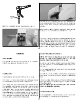
CAUTION!!!: You must use extreme care when cutting hinge
slots with a hobby knife, to avoid cutting yourself! If the balsa
part breaks while you are pushing on the knife, the blade could
go into your hand before you know it! A good precaution is to
wear leather gloves while performing the following steps and
always cut AWAY from yourself.
❍
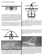
3. Insert the hinges into the slots and trial fit the Rudder and
Elevator in place on the Fin and Stabilizer. Do not glue the
hinges until after you have covered the model.
BUILD THE FUSELAGE
Fuse Side Construction
❍
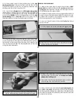
1. Cut the "Fuselage side view" section from the fuselage plan
sheet and tape it on your building board. Tape a piece of Top Flite
Plan Protector or wax paper over the plan.
❍
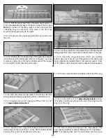
2. Glue the balsa die-cut 1/8" Upper Forward Fuse Sides to the
balsa die-cut 1/8" Lower Forward Fuse Sides using thin CA. Mark
the inside surface of the fuse sides with the letters 'R' and 'L' to
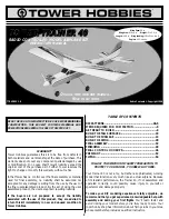
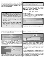
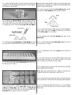
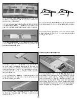
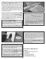
C. Trial fit the hinge into the slot. If the hinge is difficult to
push in, re-insert the knife and move it back and forth in
the slot a few times to enlarge the slot.
★★★★
Pro Tip: Hinge slotting is a procedure that is required
for every model airplane. We have found that the technique
described below is accurate and fairly easy. Just work slowly
and carefully. Remember: Hobby knives are extremely sharp!
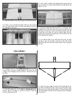
A. Begin by carefully cutting a very shallow slit at the hinge
location. This first cut is to establish your cut in the right
place, so concentrate on staying on the centerline and
don't cut too deep!
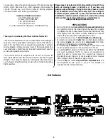
B. Make three or four more cuts in the same line, going slightly
deeper each time. As you make these additional cuts, work
on going straight into the wood. Continue this process
while "wiggling" the knife handle back and forth until the
blade has reached the proper depth for the hinge.
13
designate the inside of the Right and Left fuselage sides. Be sure
to make a RIGHT and a LEFT fuselage side. Sand both sides of
the fuse sides using 150-grit sandpaper.
❍
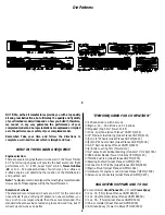
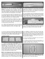
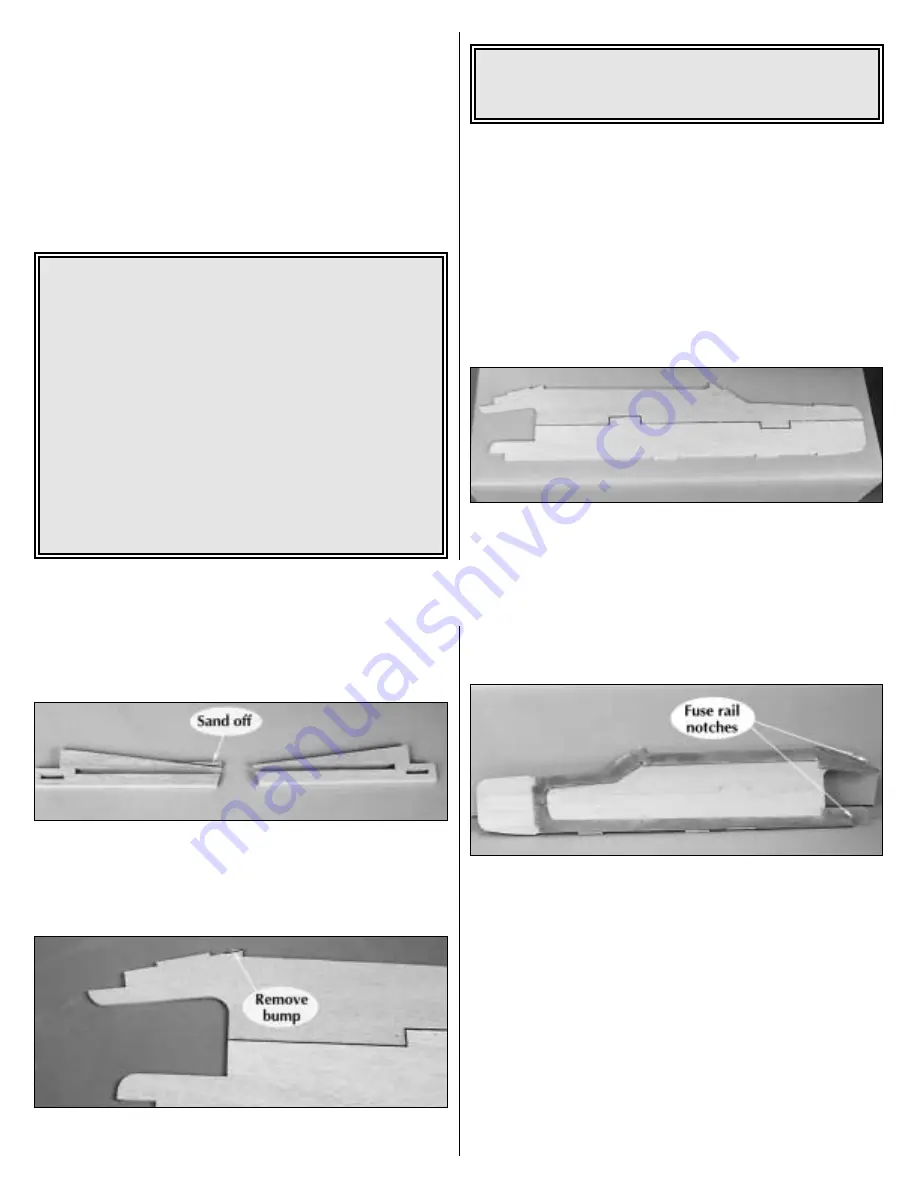
3. Locate the four die-cut 1/8" balsa Stabilizer Bases. Carefully
align and laminate two of the bases together using medium CA to
produce a 1/4" thick base. Repeat the procedure for the
remaining two bases. Sand the area shown in the photo using
120-grit sandpaper.
❍
4. Use a straightedge to mark a line along the top of both fuse
sides, as there is a slight bump necessary for the die-cutting of the
part. Use a hobby knife and/or bar sander to remove the bump.
(This bump is also on the upper fuse doubler.)
❍
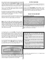
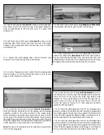
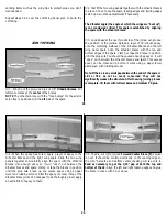
5. Locate the die-cut 1/8" plywood Upper and Lower Fuse
Doublers. Make sure you are making both a Left and Right fuse
side. Test fit them onto the fuse sides as shown in the photo. Make
any necessary adjustment to allow the doublers to fit accurately
onto the fuse sides. Once all the fitting is done, glue them in
position using Thin CA. Make sure to make both a left and right
set. Sand the notches for the balsa fuse rails to provide a smooth
glue surface.
❍
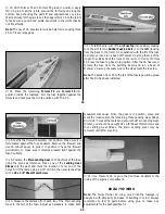
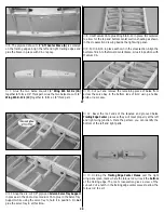
6. Place the Right Fuse Side onto the fuselage plan and pin it
in position. (The doubler should be facing away from the plan
sheet). Pin the Stabilizer Base into position on the plans.
❍
7. Use two of the 1/4"x 1/2" x 24" balsa sticks to make the upper
and lower Fuse Rails. Use medium CA to glue them into position.
Trim the excess extending past the Stabilizer Base.
14

