


2.15 Wireless LAN Troubleshooting
2 Troubleshooting Procedures
PORTEGE A200 Maintenance Manual (960 -499)
2-49
Procedure 2
Antenna Connection Check
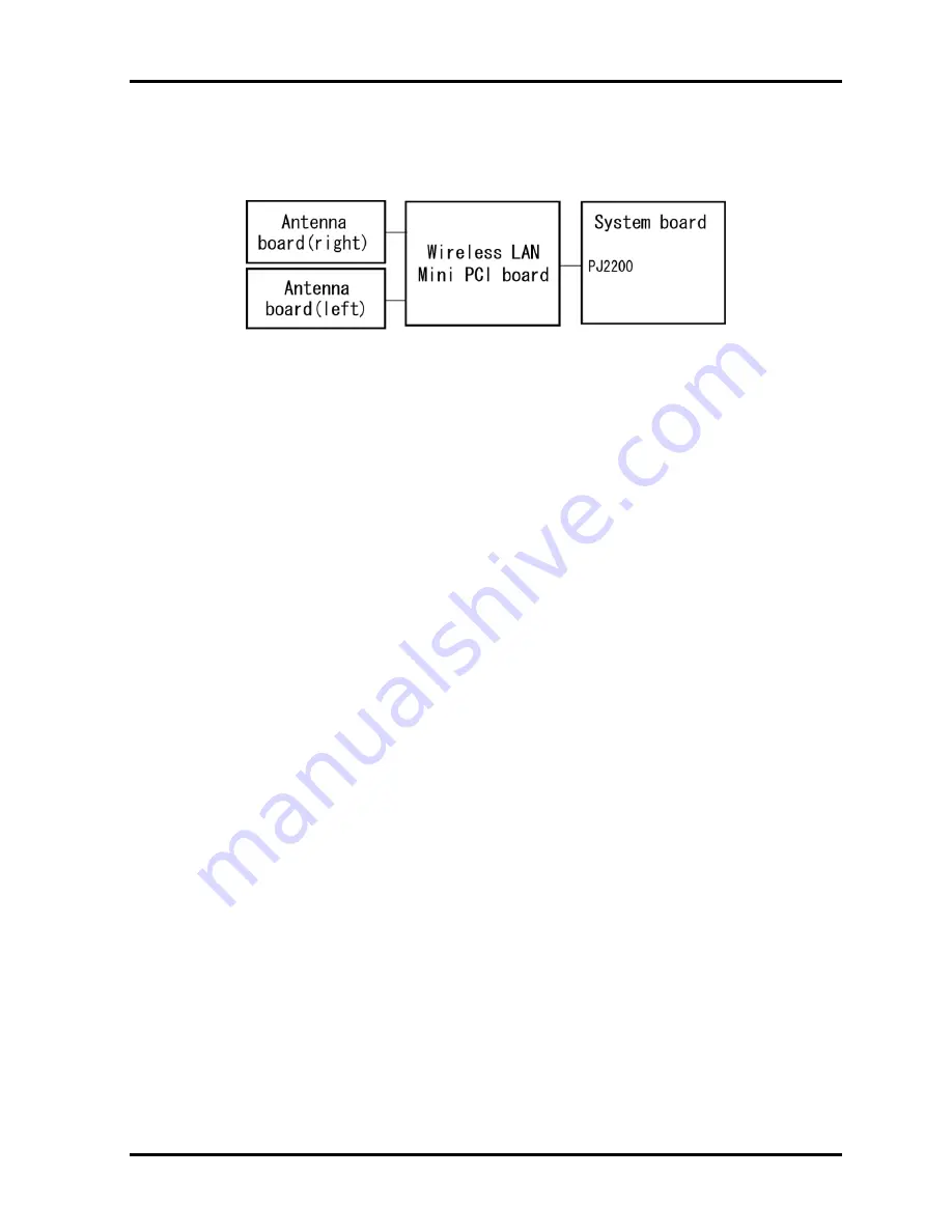
The wireless LAN function wiring diagram is shown below:
Any of the connections may be disconnected. Disassemble the computer following the steps
described in Chapter 4, perform the following checks:
Check 1
Make sure the wireless communication switch is “On”.
If the switch is “Off”, turn it “On”. If the wireless LAN is still not functioning
properly, perform Check 2.
Check 2
The wireless LAN board and the system board may be disconnected. Make sure
the wireless LAN board is firmly connected to the PJ2200 of the system board.
If the connector is disconnected, connect firmly and return to Procedure 1. If there
is still an error, go to Check 3.
Check 3
Make sure the wireless LAN antenna cables (black and white) are firmly connected
to the Wireless LAN board. If the antenna cables are disconnected, connect them
firmly then return to Procedure 1. If there is still an error, perform Procedure 3.
Procedure 3
Replacement Check
The wireless LAN board, wireless LAN antenna or the system board may be defective.
Disassemble the computer following the steps described in Chapter 4 and perform the
following checks.
Check 1
The wireless LAN board may be defective or damaged. Disassemble the computer
following the steps described in Chapter 4 and replace the board with a new one. If
there is still an error, go to Check 2.
Check 2
The wireless LAN antenna may be defective or damaged. Disassemble the
computer following the steps described in Chapter 4 and replace the board with a
new one. If there is still an error, go to Check 3.
Check 3
The system board may be defective or damaged. Disassemble the computer
following the steps described in Chapter 4 and replace the board with a new one.
Summary of Contents for Satellite A200 Series
Page 10: ...x PORTEGE A200 Maintenance Manual 960 499 ...
Page 11: ...Chapter 1 Hardware Overview ...
Page 12: ...1 Hardware Overview 1 ii PORTEGE A200 Maintenance Manual 960 499 1 Hardware Overview ...
Page 36: ...Chapter 2 Troubleshooting Procedures ...
Page 37: ...2 Troubleshooting Procedures 2 ii PORTEGE A200 Maintenance Manual 960 499 2 ...
Page 41: ...2 Troubleshooting Procedures 2 vi PORTEGE A200 Maintenance Manual 960 499 ...
Page 91: ...Chapter 3 Tests and Diagnostics ...
Page 92: ...3 Tests and Diagnostics 3 ii PORTEGE A200 Maintenance Manual 960 499 3 ...
Page 96: ...3 Tests and Diagnostics 3 vi PORTEGE A200 Maintenance Manual 960 499 ...
Page 199: ...Chapter 4 Replacement Procedures ...
Page 200: ...4 Replacement Procedures 4 ii PORTEGE A200 Maintenance Manual 960 499 4 ...
Page 278: ...Appendices ...
Page 279: ...Appendices App ii PORTEGE A200 Maintenance Manual 960 499 ...
Page 284: ...Appendices PORTEGE A200 Maintenance Manual 960 499 App vii ...
Page 290: ...Appendices Appendix A Handling the LCD Module A 6 PORTEGE A200 Maintenance Manual 960 499 ...
Page 322: ...Appendices Appendix C Pin Assignment C 26 PORTEGE A200 Maintenance Manual 960 499 ...
Page 332: ...Appendices Appendix E Key Layout E 2 PORTEGE A200 Maintenance Manual 960 499 ...
Page 334: ...Appendices Appendix F Wiring Diagrams F 2 PORTEGE A200 Maintenance Manual 960 499 ...
Page 336: ...Appendices Appendix G BIOS Rewrite Procedures G 2 PORTEGE A200 Maintenance Manual 960 499 ...
Page 338: ...Appendices Appendix H EC KBC Rewrite Procedures H 2 PORTEGE A200 Maintenance Manual 960 499 ...
Page 340: ...Appendices Appendix I Reliability I 2 PORTEGE A200 Maintenance Manual 960 499 ...
Page 342: ...Appendices Apx J Key FD J 2 PORTEGE A200 Maintenance Manual 960 499 ...


![Lenovo 90B6 [H50-50 ES] User Manual preview](http://thumbs.mh-extra.com/thumbs/lenovo/90b6-h50-50-es/90b6-h50-50-es_user-manual_201023-01.webp)


