– 67 –
No.
Part name
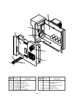
Inverter
assembly
Procedure
1) Perform works of items of 1 of
, 1 of
,
and
.
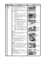
2) Disconnect connectors connected from
the cycle P.C. board to other parts.
CN600: TD sensor (3P: White)
CN601: TO sensor (2P: White)
CN604: TE sensor (2P: White) *(Note 1)
CN605: TS sensor (3P: White) *(Note 1)
CN301: Outdoor fan (3P: White) *(Note 1)
CN300: Position detection (5P: White)
CN500: Case thermo (2P: Blue) *(Note 1)
CN700: 4-way valve (3P: Yellow) *(Note 1)
CN702: PMV coil (6P: White) *(Note 1)
*(Note 1)
Unlock the lock of housing part, and then
disconnect the connectors.
3) Cut the tie lap fixing various lead wires to
the inverter assembly.
4) Remove the rubber sheet and noise-proof
plate (upper).
5) Remove terminal cover of the compressor
and Comp. lead wire.
6) Pull upward the hook (Rear left) with the
partition board as if removing it.
• Caution when attaching inverter
assembly
When installing the inverter assembly to
the partition board, attach hook (Rear
left) of the partition board surely.
Remarks
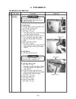
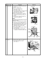
Cycle P.C. board
Inverter assembly
Rubber sheet
Comp. lead
There is a hook with the
partition board at rear side.
Noise-proof plate
(Upper)


