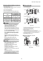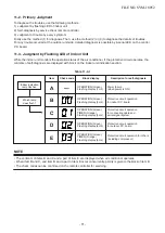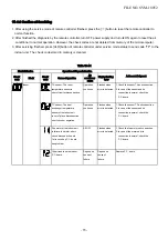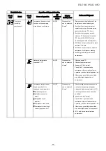
Fixing the Outdoor Unit
Fix the outdoor unit using attachment bolts.
• Use 8 mm or 10 mm anchor bolts and nuts.
• Do not allow the attachment bolts to protrude by more than 15 mm.
• Install the outdoor unit at ground level.
•
GOOD
BAD
Attach the vibration-proof rubber pads under the
fi
xing legs.
15 mm or
less
Mounting leg
Absorb vibration
with vibration-proof
rubber pads
Foundation
Foundation
If only the end
of the
mounting leg
is supported,
it may
deform.
Do not support
the outdoor unit
only with the
mounting leg.
Bottom plate of
outdoor unit
Foundation
Support the bottom surface of the
mounting leg that is in contact with
and underneath the bottom plate of
the outdoor unit.
Drain hole
Drain nipple mounting hole
Drain hole
150
150
600
525
45
365
400
Refrigerant piping
CAUTION
Install in rooms that are
13
m
3
or larger. If
a leak of refrigerant gas occurs inside the
room, an oxygen de
fi
ciency
may occur.
■
Detaching the Valve cover
Remove the 5 screws.
• Pull the
front panel
in the direction of the arrow, and remove it.
■
Refrigerant Piping Connection
Flaring
1. Cut the pipe with a pipe cutter.
Obliquity
Roughness
Warp
90°
2.
3.
4.
Remove the burr inside of the pipe.
When removing the burr, be careful so that chips do not fall into the pipe.
Remove the
fl
are nuts attached to the outdoor/indoor unit, then insert them
into each of the pipes.
Flare the pipes.
See the following table for the projection margin (A) and
fl
aring size (B).
Die
Pipe
B
A
Pipe
A
B
Outside
diameter
Thickness
Rigid
(clutch
type)
R
32
tool
Imperial
(wing
nut type)
R
32
tool
mm
mm
mm
mm
mm
6.35
0.8
0 to 0.5
1.5 to
2.0
9.1
9.52
0.8
0 to 0.5
1.5 to
2.0
13.2
12.7
0.8
0 to 0.5
2.0 to
2.5
16.6
CAUTION
•
•
Do not scratch the inner surface of the
fl
ared part when removing burrs.
Flare processing under the condition of
scratches on the inner surface of
fl
are
processing part will cause refrigerant gas
leak.
<Tightening connection>
Align the centers of the connecting pipes and tighten
the flare nut as far as possible with your fingers
. Then
tighten the nut with a spanner and torque wrench as
shown in the figure.
Use a torque wrench to tighten.
Fig.
10-
2
-
7
Flare nut
Half union
Use a wrench to secure.
Externally
threaded side
Internally
threaded side
CAUTION
Do not apply excess torque.
Otherwise, the nut may crack depending on the
conditions.
•
•
Fig. 10-
2-
6
FILE NO. SVM-18052
- 62 -
Fig. 10-2-5

