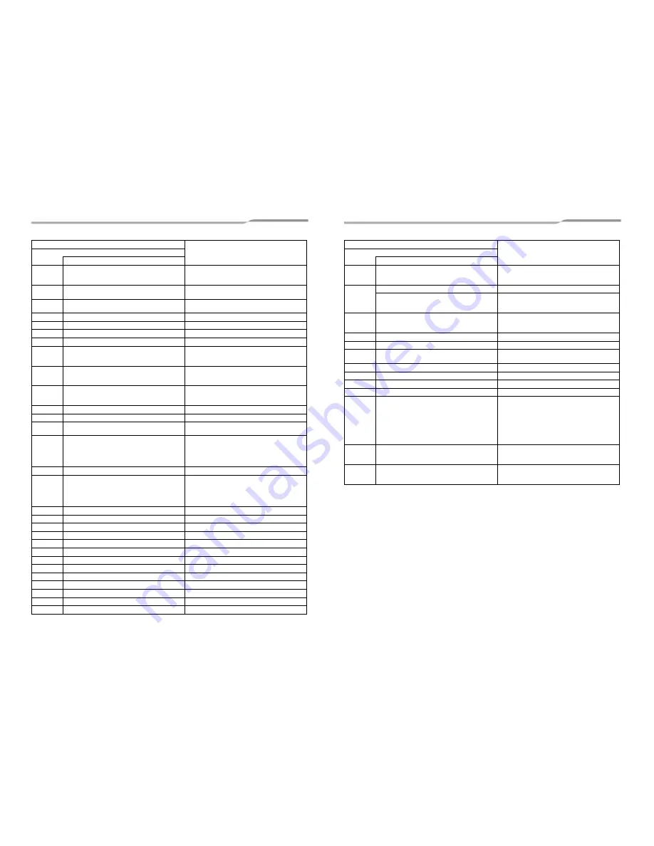
background image

– 33 –

F13

01: Compressor 1
02: Compressor 2
03: Compressor 3

TH (Heat sink) sensor error

F15

Outdoor temp. sensor miswiring
Outdoor pressure sensor miswiring (TE1, TL)

F16

Outdoor temp. sensor miswiring
Outdoor pressure sensor miswiring (Pd, Ps)

F22

TD3 sensor error

F23

Ps sensor error

F24

Pd sensor error

F31

Outdoor EEPROM error

H01

01: Compressor 1
02: Compressor 2
03: Compressor 3

Compressor breaking down

H02

01: Compressor 1
02: Compressor 2
03: Compressor 3

Compressor error (Locked)

H03

01: Compressor 1
02: Compressor 2
03: Compressor 3

Current detection circuit error

H05

TD1 sensor miswiring

H06

Low pressure protective operation

H07

Detected outdoor unit number

Oil level down detection 

(Indicated only on the header outdoor unit)

H08

01: TK1 sensor error 
02: TK2 sensor error
03: TK3 sensor error 
04: TK4 sensor error
05: TK5 sensor error

Temperature sensor error for oil level

H15

TD2 sensor miswiring

H16

01: TK1 oil circuit error
02: TK2 oil circuit error
03: TK3 oil circuit error
04: TK4 oil circuit error
05: TK5 oil circuit error

Oil level detector circuit error

H25

TD3 sensor miswiring

L02

Mismatch of the indoor unit and outdoor unit model

L04

Outdoor system address duplication

L06

Number of prior indoor units

Duplication of indoor units with priority

L08

Indoor unit group / address unset

L10

Outdoor unit capacity unset. 

L17

Mismatch of the outdoor unit model

L18

Detected indoor unit address

Flow selector unit error

L28

Outdoor connected quantity over

L29

IPDU number information

(*1)

IPDU quantity error

L30

Detected indoor unit address

External interlock of indoor unit

L31

Other compressor errors

P03

Discharge temperature TD1 error

Check code

Check code name

Indication on 7-segment display on the outdoor unit

Auxiliary code

*1

PDU number information

01:Compressor 1

02:Compressor 2

03:Compressors 1 and 2

04:Compressor 3

05:Compressors 1 and 3

06:Compressors 2 and 3

07:Compressors 1, 2 and 3

08:Fan

09:Compressor 1 and fan

0A:Compressor 2 and fan

0B:Compressors 1, 2 and fan

0C:Compressor 3 and fan

0D:Compressors 1, 3 and fan

0E:Compressors 2, 3 and fan

0F:Compressors 1, 2, 3, and fan

P04

01: Compressor 1
02: Compressor 2
03: Compressor 3

High-pressure SW system operation

P05

00: 

Phase missing / power failure detection

01: Compressor 1
02: Compressor 2
03: Compressor 3

Inverter DC voltage error (on compressor)

P07

01: Compressor 1
02: Compressor 2
03: Compressor 3

Heat sink overheat error

P10

Detected indoor unit address

Indoor overflow error

P13

Outdoor unit flow back error detected

P15

01: TS condition
02: TD condition

Gas leak detection

P17

Discharge temperature TD2 error

P18

Discharge temperature TD3 error

P19

Detected outdoor unit number

4-way valve inverse error

P20

High-pressure protective operation

P22

0 *: IGBT circuit
1 *: Position detection circuit error
3 *: Motor lock error
4 *: Motor current detected
C *: TH sensor temperature error
D *: TH sensor error
E *: Inverter DC voltage error

(outdoor unit’s fan)

Outdoor fan IPDU error

(NOTE)

Ignore 0-F appearing in the position of “*”.

P26

01: Compressor 1
02: Compressor 2
03: Compressor 3

G-TR short protection error

P29

01: Compressor 1
02: Compressor 2
03: Compressor 3

Compressor position detecting circuit error

Check code

Check code name

Indication on 7-segment display on the outdoor unit

Auxiliary code

65-EN

66-EN

Summary of Contents for MMY-MAP0804FT8-E

Page 1: ...me MMY MAP0804FT8 E MMY MAP1004FT8 E MMY MAP1204FT8 E MMY MAP1404FT8 E MMY MAP0804FT8Z E MMY MAP1004FT8Z E MMY MAP1204FT8Z E MMY MAP1404FT8Z E MMY MAP0804FT8ZG E MMY MAP1004FT8ZG E MMY MAP1204FT8ZG E MMY MAP1404FT8ZG E Installation Manual For commercial use ...

Page 2: ...e 6 5 Carrying in the outdoor unit 7 6 Installation of the outdoor unit 8 7 Refrigerant piping 10 8 Electric wiring 19 9 Address setting 23 10 How to set up the cooling only indoor unit 30 11 Test run 31 12 Troubleshooting 32 13 Machine card and logbook 34 ADOPTION OF NEW REFRIGERANT This Air Conditioner uses R410A an environmentally friendly refrigerant 1 EN 2 EN ...

Page 3: ...k at heights has been trained in matters relating to working at heights with the air conditioners made by Toshiba Carrier Corporation or alternatively he or she has been instructed in such matters by an individual or individuals who have been trained and is thus thoroughly acquainted with the knowledge related to this work Qualified service person The qualified service person is a person who insta...

Page 4: ...nditioner If the compressor is operated with the valve open and without refrigerant pipe the compressor sucks air and the refrigeration cycles is over pressurized which may cause a injury Tighten the flare nut with a torque wrench in the specified manner Excessive tighten of the flare nut may cause a crack in the flare nut after a long period which may result in refrigerant leakage Ventilate the a...

Page 5: ...ied Installer or Qualified Service Person CAUTION New refrigerant air conditioner installation This air conditioner adopts the new HFC refrigerant R410A which does not destroy ozone layer The characteristics of R410A refrigerant are easy to absorb water oxidizing membrane or oil and its pressure is approx 1 6 times higher than that of refrigerant R22 Accompanied with the new refrigerant refrigerat...

Page 6: ...former refrigerant by approximately 1 6 times As well as the adoption of the new refrigerant the refrigerating oil has been also changed Therefore pay attention so that water dust former refrigerant or refrigerating oil does not enter the refrigerating cycle of the new refrigerant air conditioner during installation To prevent mixing of refrigerant or refrigerating oil the size of the charge port ...

Page 7: ...ent temperature falls below 15 C for more than 72 hours running The outdoor heat exchanger may be damaged by the frost The cooling performance may decline considerably when total operating capacity of cooling indoor units is less than 4HP while ambient temperature is below 0 C Installation space Leave space necessary for running installation and servicing NOTE If there is an obstacle above the out...

Page 8: ... comes into contact with the outdoor unit so that no damage is caused to the outer surface of the outdoor unit There are reinforcing plates on the side surfaces so the rope cannot be passed through Front Back GOOD NO GOOD NO GOOD Plaster Rope Plaster Rectangular holes for lifting Reinforcing plate Prongs of the forklift Rectangular holes for handling GOOD NO GOOD Side Weight centre and weight Weig...

Page 9: ...and the air discharge Leave enough space for the snowfall hood so that it will not be an obstacle for the air intake and the air discharge 1 To install multiple outdoor units arrange them with 20 mm or more spaces in between Fix each outdoor unit with M12 anchor bolts at 4 positions 20 mm projection is appropriate for an anchor bolt Snowfall hood for air discharge locally procured Snowfall hood fo...

Page 10: ... 15 degrees Horizontal line Within 15 degrees Horizontal line A arrow view At a level position B arrow view Do not connect a branch unit vertically Header unit A Follower unit B Follower unit C Main pipe To indoor unit Liquid joint Discharge gas joint Good Header unit A Follower unit B Follower unit C To indoor unit Main pipe No Good Liquid joint Discharge gas joint Suction gas pipes Suction gas j...

Page 11: ...a brazing work of the refrigerant pipes be sure to use nitrogen gas in order to prevent oxidation of the inside of the pipes otherwise clogging of the refrigerating cycle due to oxidized scale may occur Use clean and new pipes for the refrigerant pipes and perform piping work so that water or dust does not contaminate the refrigerant Remove all flux after brazing Be sure to use a double spanner to...

Page 12: ...pipe Liquid pipe Suction side gas pipe Suction side gas pipe Section to be cut L shaped pipe Socket Pipe Pipe Attachment pipe Attachment pipe Pipe Socket Socket B Extruding margin of copper pipe with flare tools A Unit mm When using the conventional flare tool to connect R410A pipes with flaring make a margin approx 0 5 mm longer than that of an R22 pipe so that the flare size matches the one spec...

Page 13: ...HP 56 33 AP2214 22 HP 61 5 37 AP2414 24 HP 68 40 AP2614 26 HP 73 43 AP2814 28 HP 78 5 47 AP3014 30 HP 85 48 AP3214 32 HP 90 48 AP3414 34 HP 96 48 AP3614 36 HP 101 48 AP3814 38 HP 106 5 48 AP4014 40 HP 112 48 AP4214 42 HP 118 48 NOTE Compared with the capacity code of the outdoor unit the total value of capacity codes of the connectable indoor units differs based on the height difference between th...

Page 14: ...flow selector unit and the dedicated cooling circuit 3 Select the branch pipe of the first branch according to the outdoor capacity code 4 Select according to the outdoor unit capacity code if the total of the indoor capacity codes exceeds the outdoor unit capacity code 5 It is possible to select up to a maximum capacity code total AP056 6 hp for the first circuit after the header branch When usin...

Page 15: ...etween outdoor units LO 15 m System restriction Limit on connecting multiple indoor units to flow selector unit Cautions for installation Set the outdoor unit first connected to the bridging pipe to the indoor units as the header unit Install the outdoor units in order of their capacity codes A header unit B C When connecting gas pipes to indoor units use Y shaped branching joints to keep pipes le...

Page 16: ... m Airtightness test After the refrigerant piping has been finished execute an airtight test For an airtight test connect a nitrogen gas canister as shown in the figure below and apply pressure Be sure to apply pressure from the service ports of the packed valves or ball valves at the liquid side discharge gas side suction gas side and balance pipe side An airtight test can only be performed at th...

Page 17: ...ing of refrigerant To protect the world s environment do not release chlorofluorocarbons into the atmosphere Do not do an air purge including used refrigerant P VL VH Connected to indoor unit Main pipe Low pressure gauge High pressure gauge Brazed Fully closed Fully closed Connected to other follower units Balanced pipe side valve fully closed Service port Vacuum pump Gauge manifold Service port H...

Page 18: ...MAP1404 MAP1204 11 42 HP AP4214 MAP1404 MAP1404 MAP1404 12 5 Full opening of the valve Open the valves of the outdoor unit fully After opening the valves fully be sure to close the caps When you close the valve shaft its cap and service port cap see below chart MAP080 MAP100 MAP120 MAP140 Balance pipe Ø9 5 packed valve Using a 4 mm hexagonal wrench fully open the valve shaft Liquid side Ø12 7 pack...

Page 19: ...ns for refrigerant leaks may be required depending on European or local legislation 7 Contact dealers installers etc for any questions R410A kg kg kg Pre charged Refrigerant at Factory kg specified in the nameplate Additional Charge on Installation Site kg Heat insulation for pipe Apply heat insulation of pipe separately at the liquid gas and balance sides Be sure to use heat insulator resistant u...

Page 20: ...pipes has finished Refer to the installation manuals of indoor unit and flow selector unit for power wiring and communication wiring of indoor unit and flow selector unit Power supply specifications Do not bridge the power between outdoor units through the equipped terminal blocks L1 L2 L3 N Power supply for outdoor units NO GOOD Power wiring selection Standard model MCA Minimum Circuit Amps MOCP ...

Page 21: ... Group control Control wiring between indoor units Shield wire Flow selector unit Flow selector unit Flow selector unit Flow selector unit Be sure to keep the rule of below tables about size and length of communication wiring 1 Total length of Communication wiring length for all refrigerant circuits L1 L2 L3 L4 Table 1 Communication wiring between indoor and outdoor units L1 L2 L3 Central control ...

Page 22: ...ut for the power wire Knockout for the communication wire Power supply wire connection 1 Insert the power supply wire through the cutout on the side of the electrical control box and connect the power supply wire to the power supply terminal block and the earth wire to the earth screw After that fix the power supply wire with the 2 cord clamps 2 Be sure to use round type crimping terminals for pow...

Page 23: ...s greater than or equal to Ssc 1 at the interface point between the user s supply and the public system It is the responsibility of the installer or user of the equipment to ensure by consultation with the distribution network operator if necessary that the equipment is connected only to a supply with a short circuit power Ssc greater than or equal to Ssc 1 Furthermore when similar equipment or ot...

Page 24: ...rocedure 2 Example When controlling a single refrigerant line centrally When controlling 2 or more refrigerant lines centrally Address setting procedure To procedure 1 To procedure 2 System wiring diagram Access door cover Fixing screw for the access door cover Cover of the electrical control box Outdoor Indoor Indoor Indoor Indoor Outdoor Central remote controller Central remote controller Remote...

Page 25: ...ol Factory default disconnected 3 Turn on indoor units first and then turn on outdoor units 4 About 1 minute after turning the power on confirm that the 7 segment display on the interface P C board of the header outdoor unit indicates 5 Press SW 15 to start the automatic address setting It may take up to 10 minutes normally about 5 minutes to complete one line s setting 6 The 7 segment display ind...

Page 26: ...er unit Follower unit Header unit Follower unit Header unit Factory default SW13 14 Line system address 1 No setting required 2 No setting required 3 1 Dip switch 2 of SW30 Terminator of indoor outdoor communication line and central control line ON No setting required Set to OFF after setting addresses No setting required Set to OFF after setting addresses ON Relay connector Connect after setting ...

Page 27: ...oor unit address 5 Push the TEMP buttons repeatedly to set the CODE No to 6 Push the TIME buttons repeatedly to set an indoor unit address 7 Push the button It is OK if the display turns on Group address 8 Push the TEMP buttons repeatedly to set the CODE No to 9 Push the TIME buttons repeatedly to set a group address If the indoor unit is individual set the address to header unit follower unit 10 ...

Page 28: ...r units in a single refrigerant line When an outdoor unit is selected the indoor unit numbers of the refrigerant line of the selected unit are indicated one after another and the fan and louvers of the indicated indoor units are activated 1 Push and hold the TIME and buttons at the same time for more than 4 seconds At first the line 1 and CODE No Address Change are indicated on the LCD display Sel...

Page 29: ...ET CL FILTER RESET TEST TIMER SET CODENo UNIT No SETTING DATA SET R C No 2 Cancels the line selection CL TEST SWING FIX SET 4 Push the TIME buttons repeatedly to change the value of the indoor unit address in SET DATA Change the value in SET DATA to that of a new address 5 Push the button to confirm the new address on SET DATA 6 Push the button left side of the button repeatedly to select another ...

Page 30: ...ntrol controller Header unit Follower unit Follower unit Remote controller Remote controller Remote controller Remote controller Indoor units to have their addresses initialized Header unit Header unit Setting when connecting multiple indoor units to a FS Flow Selector unit Cautions to connection of indoor unit When connecting the multiple indoor units to a single FS unit it is necessary to set up...

Page 31: ...it No in the group control is displayed successively In this time the position of the indoor unit of which setup is to be changed can be confirmed because the fan and louver of the selected indoor unit work 3 Use and buttons of the set temperature to specify the CODE No 0F 4 Use and buttons of the timer time to select the setup data 0001 5 Push button In this time if the display changes from flash...

Page 32: ...unning after finishing the trial run The indication on the LCD display returns to the status of procedure 1 5 Push the button to exit the trial mode TEST disappears on the LCD display and the status changes to normal stopped mode 1 5 3 2 4 ON OFF TEMP TIME SET CL FILTER RESET TEST TIMER SET TEST TEST ON OFF MODE TEST ON OFF TEST When executing a test run using the interface P C board on the outdoo...

Page 33: ...unit Indicated when SW01 1 SW02 1 and SW03 1 Rotary switch setting value Indication LED SW01 SW02 SW03 1 1 1 Outdoor unit check code A Outdoor unit number U1 to U3 B Check code display Check code Check code name Indication on 7 segment display on the outdoor unit Auxiliary code E06 Number of indoor units which received normally Decrease of number of indoor units E07 Indoor outdoor communication ci...

Page 34: ...t address External interlock of indoor unit L31 Other compressor errors P03 Discharge temperature TD1 error Check code Check code name Indication on 7 segment display on the outdoor unit Auxiliary code 1PDU number information 01 Compressor 1 02 Compressor 2 03 Compressors 1 and 2 04 Compressor 3 05 Compressors 1 and 3 06 Compressors 2 and 3 07 Compressors 1 2 and 3 08 Fan 09 Compressor 1 and fan 0...

Page 35: ...burn centres Logbook Update the log periodically after maintenance as defined in EN378 4 Describe the following items on the logbook 1 details of the maintenance and repair works 2 quantities kind of new reused recycled refrigerant which have been charged on each occasion the quantities of refrigerant which have been transferred from the system on each occasion see also EN378 4 3 if there is an an...

Page 36: ...tioners is 0 3 kg m3 NOTE 1 If there are 2 or more refrigerating systems in a single refrigerating device the amounts of refrigerant should be as charged in each independent device For the amount of charge in this example The possible amount of leaked refrigerant gas in rooms A B and C is 10 kg The possible amount of leaked refrigerant gas in rooms D E and F is 15 kg NOTE 2 The standards for minim...

Page 37: ...EH99889397 ...

Reviews: