background image

– 17 –  

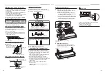
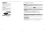
8

1, 7

Slide 

Air intake grille 

fi

 xing knob 

Air 

fi

 lter 

 Air intake grille 

Air 

fi

 lter handle 

Air 

fi

 lter 

Air 

fi

 lter handle 

Air intake grille hook 

Air intake grille 

fi

 xing hook 

Air intake grille 

fi

 xing knob 

Air intake grille 

Air 

fi

 lter 

10

 Maintenance 

<Daily maintenance> 

Cleaning of air 

fi

 lter 

• If   is displayed on the remote controller, maintain 

the air 

fi

 lter. 

1

Push the 

 button to stop the operation, 

then turn off the circuit breaker. 

Periodic Maintenance 

•  For environmental conservation, it is strongly recommended that the indoor and outdoor units of the air 

conditioner in use be cleaned and maintained regularly to ensure ef

fi

 cient operation of the air conditioner. When 

the air conditioner is operated for a long time, periodic maintenance (once a year) is recommended. Furthermore, 
regularly check the outdoor unit for rust and scratches, and remove them or apply rustproof treatment, if 
necessary. 
As a general rule, when an indoor unit is operated for 8 hours or more daily, clean the indoor unit and outdoor unit 
at least once every 3 months. Ask a professional for this cleaning / maintenance work. Such maintenance can 
extend the life of the product though it involves the owner’s expense. 
Failure to clean the indoor and outdoor units regularly will result in poor performance, freezing, water leakage, and 
even compressor failure.

Inspection before maintenance 

Following inspection must be carried out by a quali

fi

 ed installer or quali

fi

 ed service person. 

Parts

Inspection method

Heat exchanger

Look through the air discharge port to check the part. Examine the heat exchanger if there 
is any clogging or damages.

Fan motor

Check if any abnormal noise can be heard.

Fan

Check if any abnormal noise can be heard.

Filter

Go to installed location and check if there are any stains or breaks on the 

fi

 lter.

Drain pan

Look through the air discharge port to check the part. Check if there is any clogging or drain 
water is polluted.

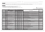
Maintenance List

Part

Unit

Check (visual / auditory)

Maintenance

Heat exchanger

Indoor / outdoor

Dust / dirt clogging, scratches

Wash the heat exchanger when it is 
clogged.

Fan motor

Indoor / outdoor

Sound

Take appropriate measures when 
abnormal sound is generated.

Filter

Indoor

Dust / dirt, breakage

• Wash the 

fi

 lter with water when it is 

contaminated.

•  Replace it when it is damaged.

Fan

Indoor

• Vibration, balance
•  Dust / dirt, appearance

•  Replace the fan when vibration or 

balance is terrible.

•  Brush or wash the fan when it is 

contaminated.

Air intake / 
discharge grilles

Indoor / outdoor

Dust / dirt, scratches

Fix or replace them when they are 
deformed or damaged.

Drain pan

Indoor

Dust / dirt clogging, drain 
contamination

Clean the drain pan and check the 
downward slope for smooth drainage.

Ornamental panel, 
louvres

Indoor

Dust / dirt, scratches

Wash them when they are 
contaminated or apply repair coating.

Exterior

Outdoor

•  Rust, peeling of insulator
•  Peeling / lift of coat

Apply repair coating.

33-EN 

34-EN 

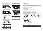
3

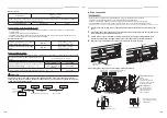
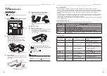
Take out air 

fi

 lter. 

•  Push the handle of the air 

fi

 lter, and remove the 

hook of the air intake grille. Pull out the air 

fi

 lter 

toward you.

4

Cleaning with water or vacuum cleaner. 

•  If dust is heavy, wash it with tepid water 

including neutral detergent or water. 

•  After cleaning with water, dry it completely in the 

shade. 

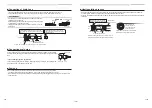
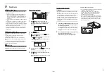
5

Mount the air 

fi

 lter. 

6

Close the air intake grille. 

•  Close the air intake grille, and then 

fi

 x it securely 

while sliding knob closed side (CLOSE). 

•  Fix the screws of air intake grille 

fi

 xing knob on a 

side of each 

fi

 lter. 

7

Turn on the circuit breaker, then push the 

 button on the remote controller to start 

the operation. 

8

After cleaning, push  .

 display disappears. 

 CAUTION

•  Do not start the air conditioner while leaving air 

fi

 lter 

removed. 

• Push the 

fi

 lter reset button. (  indication will be turn 

off.) 

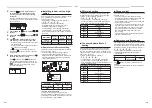
2

Open the air intake grille. 

•  Remove the screws of air intake grille 

fi

 xing 

knob on a side of each 

fi

 lter. 

•  Slide the air intake grille 

fi

 xing knobs (two 

positions) toward the arrow direction (OPEN), 
and then open the air intake grille. 

Summary of Contents for MMC-AP0157HP-E (TR)

Page 1: ...NDITIONER MULTI TYPE Installation Manual For commercial use English Indoor Unit Model name Ceiling Type MMC AP0157HP E MMC AP0187HP E MMC AP0247HP E MMC AP0277HP E MMC AP0367HP E MMC AP0487HP E MMC AP0567HP E ...

Page 2: ... 10 Maintenance 17 11 Troubleshooting 18 12 Specifications 23 Please read this Installation Manual carefully before installing the Air Conditioner This Manual describes the installation method of the indoor unit For installation of the outdoor unit follow the Installation Manual attached to the outdoor unit ADOPTION OF NEW REFRIGERANT This Air Conditioner uses R410A an environmentally friendly ref...

Page 3: ...ted to this work The qualified installer who is allowed to do the refrigerant handling and piping work involved in installation relocation and removal has the qualifications pertaining to this refrigerant handling and piping work as stipulated by the local laws and regulations and he or she is a person who has been trained in matters relating to refrigerant handling and piping work on the air cond...

Page 4: ...ndertake work at heights using a stand of 50 cm or more or to remove the intake grille of the indoor unit to undertake work Wear protective gloves and safety work clothing during installation servicing and removal Do not touch the aluminium fin of the unit You may injure yourself if you do so If the fin must be touched for some reason first put on protective gloves and safety work clothing and the...

Page 5: ...or short circuit Test run Before operating the air conditioner after having completed the work check that the electrical control box cover of the indoor unit and service panel of the outdoor unit are closed and set the circuit breaker to the ON position You may receive an electric shock if the power is turned on without first conducting these checks If there is any kind of trouble such as an error...

Page 6: ...ps or other moving conveyances The air conditioner must not be used for special applications such as for storing food plants precision instruments or art works The quality of the items stored may be degraded Locations where high frequencies are generated by inverter equipment in house power generators medical equipment or communication equipment Malfunctioning or control trouble in the air conditi...

Page 7: ...ess remote controller kit sold separately The signal of the wireless type remote controller can be received within approx 8 m This distance is a criterion and varies a little according to capacity of the battery To prevent malfunction select a place where is not affected by a fluorescent lamp or direct sunlight Two wireless type indoor units can be set in a room 4 Installation Model MMC Possible i...

Page 8: ... Use M10 hanging bolts 4 pcs locally procured Matching to the existing structure set pitch according to size in the External dimensions Installation of remote controller Sold separately For installation of the remote controller follow the Installation Manual attached with the remote controller Pull out the remote controller cord together with the refrigerant pipe or drain pipe Pass the remote cont...

Page 9: ...ase of taking pipe from upper side Taking pipe from upper side is applied only to the refrigerant pipe When taking out the drain pipe from the upper side use a drain up kit sold separately Open the upper pipe draw out port Knockout hole shown in the external dimensions Make the diagonally shaded hole when you do not use the Elbow Piping Kit Make only this knockout hole when you use the separately ...

Page 10: ...any air vents Otherwise the drain water will spout causing water to leak Do not allow any force to be applied to the connection area with the drain pipe A hard PVC pipe cannot be connected to the drain pipe connecting port of the indoor unit Be absolutely sure to use the flexible hose provided for the connections with the drain pipe connecting port Adhesive agents cannot be used for the drain pipe...

Page 11: ...e of taking pipe from the left side In case of taking pipe from the left side exchange the plug from left to right Push in the plug of which end is not sharp up to the end Drain up When a down gradient cannot be secured for the drain pipe drain up piping is possible The height of the drain pipe must be 600 mm or less from the underside of the indoor unit When Drain Pump Kit sold separately is inst...

Page 12: ... the refrigerant of specified amount REQUIREMENT Charging an excessive or too little amount of refrigerant causes a trouble of the compressor Charge the refrigerant of specified amount A personnel who charged the refrigerant should write down the pipe length and the added refrigerant amount in the F GAS label of the outdoor unit It is necessary to fix the compressor and refrigeration cycle malfunc...

Page 13: ... of the indoor unit prepare the exclusive power supply separated from that of the outdoor unit Arrange the power supply circuit breaker and main switch of the indoor unit connected to the same outdoor unit so that they are commonly used Power supply wire specification Cable 3 core 2 5 mm in conformity with Design 60245 IEC 57 CAUTION If incorrect incomplete wiring is carried out it will cause an e...

Page 14: ...wer supply wiring fuse rating for indoor units should be selected by the accumulated total current values of the indoor units Power supply wiring Below 50 m 2 5 mm2 Control wiring Central controller wiring 2 core with polarity wires are used for the Control wiring between indoor unit and outdoor unit and Central controller wiring To prevent noise trouble use 2 core shield wire The length of the co...

Page 15: ...Remote controller Indoor unit Indoor unit Control wiring between outdoor units Control wiring between indoor and outdoor units Control wiring between indoor units Earth leakage breaker Outdoor Power supply 380 415 V 50 Hz 380 V 60 Hz 1 Push and hold button and TEMP button simultaneously for at least 4 seconds After a while the display flashes as shown in the figure Confirm that the CODE No is 01 I...

Page 16: ...edure and wiring method of the individual line Identical refrigerant line system refer to Electrical connection in this Manual Wiring between indoor units in a group is performed in the following procedure Connect the indoor units by connecting the remote controller inter unit wires from the remote controller terminal blocks A B of the indoor unit connected with a remote controller to the remote c...

Page 17: ...ble for trial runs To perform a test run set the unit to heating mode with the remote controller The unit might not operate in heating mode however depending on temperature conditions 1 Hold down the TEMPORARY button for over 10 seconds With a beep sound the unit is set to the forced cooling mode In approximately three minutes it is forced to start in cooling mode Determine that cool air comes out...

Page 18: ...eck if there is any clogging or drain water is polluted Maintenance List Part Unit Check visual auditory Maintenance Heat exchanger Indoor outdoor Dust dirt clogging scratches Wash the heat exchanger when it is clogged Fan motor Indoor outdoor Sound Take appropriate measures when abnormal sound is generated Filter Indoor Dust dirt breakage Wash the filter with water when it is contaminated Replace...

Page 19: ...log can be confirmed from both operating status and stop status 1 When and buttons are pushed simultaneously for 4 seconds or more the following display appears If is displayed the mode enters in the error log mode 01 Order of error log is displayed in CODE No Error code is displayed in CHECK Indoor unit address in which an error occurred is displayed in Unit No 2 Every pushing of button used to s...

Page 20: ...tion circuit error between indoor outdoor unit Detected at indoor unit side Indoor unit E06 E06 No of indoor units in which sensor has been normally received Decrease of No of indoor units I F E07 Communication circuit error between indoor outdoor unit Detected at outdoor unit side I F E08 E08 Duplicated indoor unit addresses Duplicated indoor unit addresses Indoor unit I F E09 Duplicated master r...

Page 21: ...ALT Ps sensor error I F F24 F24 ALT Pd sensor error I F F29 SIM Indoor unit other error Indoor unit F31 F31 SIM Indoor unit EEPROM error I F H01 H01 01 Comp 1 side 02 Comp 2 side 03 Comp 3 side Compressor break down IPDU H02 H02 01 Comp 1 side 02 Comp 2 side 03 Comp 3 side Compressor trouble lock IPDU H03 H03 01 Comp 1 side 02 Comp 2 side 03 Comp 3 side Current detect circuit system error IPDU H04...

Page 22: ... unit L31 Extended I C error I F P01 ALT Indoor fan motor error Indoor unit P03 P03 ALT Discharge temp TD1 error I F P04 P04 01 Comp 1 side 02 Comp 2 side 03 Comp 3 side ALT High pressure SW system operation IPDU P05 P05 00 01 Comp 1 side 02 Comp 2 side 03 Comp 3 side ALT Phase missing detection Power failure detection Inverter DC voltage error comp Inverter DC voltage error comp Inverter DC volta...

Page 23: ...06 Comp 2 Comp 3 07 Comp 1 Comp 2 Comp 3 08 Fan 09 Comp 1 Fan 0A Comp 2 Fan 0B Comp 1 Comp 2 Fan 0C Comp 3 Fan 0D Comp 1 Comp 3 Fan 0E Comp 2 Comp 3 Fan 0F Comp 1 Comp 2 Comp 3 Fan Error detected by TCC LINK central control device Check code Wireless remote controller Check code name Judging device Wired remote controller display Outdoor unit 7 segment display Sensor block display of receiving uni...

Page 24: ...ited Kingdom Hereby declares that the machinery described below Generic Denomination Air Conditioner Model type MMC AP0157HP E MMC AP0187HP E MMC AP0247HP E MMC AP0277HP E MMC AP0367HP E MMC AP0487HP E MMC AP0567HP E Commercial name Super Modular Multi System Air Conditioner Super Heat Recovery Multi System Air Conditioner Mini Super Modular Multi System Air Conditioner MiNi SMMS series Complies w...

Page 25: ... Min volume of the indoor unit installed room m3 Concentration limit kg m3 The concentration limit of R410A which is used in multi air conditioners is 0 3 kg m3 NOTE 1 If there are 2 or more refrigerating systems in a single refrigerating device the amounts of refrigerant should be as charged in each independent device Important 2 When there is an effective opening with the adjacent room for venti...

Page 26: ...1114652499 ...

Reviews: