


58
4200FA Installation and Operation Manual
6.19
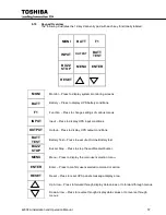
Key Functions
6.19.1 MONI
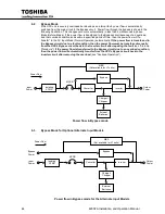
After the UPS has been successfully started, the system will be in the normal 'AC Input
Mode' of operation. The LCD screen will automatically display the main MONI (monitor)
function. If the MONI key is pressed at this time the screen output will not change. The
MONI function automatically monitors the entire UPS system. The LCD screen will
automatically switch "off" after a period of keypad inactivity and switch "on" if any key is
pressed. It will switch "on" automatically during battery discharge or if an abnormality
develops in the system (see "Settings for LCD Display Duration"). All system 'line'
messages will be displayed from MONI mode when abnormal operating problems are
detected. If AC input power is available and the UPS is operating normally, the following
system message is displayed:
- UPS ON-LINE -
OUTPUT VOLTAGE= 208 V
CURRENT=100/100/99%
DATE (DAY) TIME
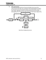
If an AC input power failure occurs, and no abnormal operating conditions are present, the
UPS switches to standard 'Battery Backup Mode'. The following system message is
displayed:
- BATTERY BACKUP –
OUTPUT VOLTAGE = 208 V
CURRENT=100/100/99%
DATE (DAY) TIME
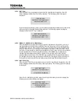
6.19.2 IN
When the IN key is pressed during normal 'AC Input Mode' of operation, the LCD screen
displays details about the unit's input voltage. The following system message is displayed:
- UPS ON-LINE -
INPUT Vab = 96%
VOLTAGE Vbc = 96%
Vca = 96%
The Bypass Input Voltages, Frequencies / Sync Mode, and Converter Current can be
monitored by pressing the "UP/DOWN" keys.
6.19.3 OUT
When the OUT key is pressed during normal ‘AC Input Mode’ of operation, the LCD screen
displays details about the output voltage, current, and frequency. The following system
message is displayed:
- UPS ON-LINE -
OUTPUT Ia = 100%
CURRENT Ib = 100%
Ic = 100%
The Output Line Voltages (phase-neutral, and phase to phase),
Frequencies / Sync Mode, Inverter Output Power, and Power factor can be monitored by
pressing the "up/down" keys.
Summary of Contents for 4200FA CT
Page 2: ...4200FA Installation and Operation Manual ...
Page 4: ...4200FA Installation and Operation Manual ...
Page 10: ...iv 4200FA Installation and Operation Manual This Page Intentionally Left Blank ...
Page 14: ...4 4200FA Installation and Operation Manual NOTE This Label for Battery Units Only ...
Page 85: ...4200FA Installation and Operation Manual 75 APPENDIX A Seismic Anchorages ...
Page 86: ...76 4200FA Installation and Operation Manual ...
Page 87: ...4200FA Installation and Operation Manual 77 ...
Page 88: ...78 4200FA Installation and Operation Manual ...
Page 96: ......
Page 97: ......


