


4200FA Installation and Operation Manual
31
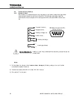
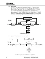
4.5.2
RS-232C
The RS-232C serial communication interface is available through a DB9 female connector located
on the inside of the UPS.
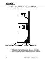
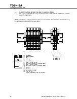
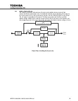
RemotEye II Mounting Location – 15-30kVA
RemotEye II Mounting Location – 50kVA
This interface allows control of the UPS from a computer network running TOSHIBA RemotEyeII
software. The computer and the UPS are connected through a serial RS-232C communication port.
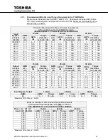
The available data from the UPS, via the RS-232C communication link, is shown below:
Operating Conditions
Input Voltage
Output Voltage
Input Frequency
Output Frequency
Battery Voltage
Output Current
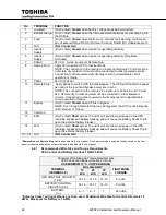
UPS Operating Status
(Described as “yes or “no”)
Utility Power OK
Low Battery Voltage Detected
UPS in BYPASS Mode
UPS in NORMAL Mode
Input and Output Frequency Synchronized
UPS FAULT Occurred
Fault Details
(Described as “occurred” or “not occurred”)
DC Bus Over-Current
DC Bus Over-Voltage
DC Bus Under-Voltage
Input Over-Current
Overheat
Overload Being Timed
Overload (allowable time exceeded)
Output Over-Voltage (during Normal Mode)
Output Under-Voltage (during Normal Mode)
RemotEye II
Module
Summary of Contents for 4200FA CT
Page 2: ...4200FA Installation and Operation Manual ...
Page 4: ...4200FA Installation and Operation Manual ...
Page 10: ...iv 4200FA Installation and Operation Manual This Page Intentionally Left Blank ...
Page 14: ...4 4200FA Installation and Operation Manual NOTE This Label for Battery Units Only ...
Page 85: ...4200FA Installation and Operation Manual 75 APPENDIX A Seismic Anchorages ...
Page 86: ...76 4200FA Installation and Operation Manual ...
Page 87: ...4200FA Installation and Operation Manual 77 ...
Page 88: ...78 4200FA Installation and Operation Manual ...
Page 96: ......
Page 97: ......


